| Author |
 Topic Topic  |
|
Stanley
Local Historian & Old Fart


36804 Posts

|
|
 Posted -
29/07/2011
:
06:27 Posted -
29/07/2011
:
06:27
|
New start as old topic was getting too big. Here's the LINK for the original topic.
Sheds are centres of honest endeavour and sanity, rare things these days. Please join in and tell us what you are doing in your shed. All are welcome!
[By the way, if I occasionally seem to be stating the bleeding obvious, it's because I'm aware of the fact that not everybody has the same experience so please forgive me.]
Stanley Challenger Graham

Barlick View
stanley at barnoldswick.freeserve.co.uk
|
|
| Replies |
| Author |
|
|
Stanley
Local Historian & Old Fart
36804 Posts
|
|
Posted - 22/08/2011 : 06:07
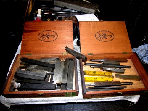
First job on the cards today was making studs for the pedestals. Nothing looks worse than ragged ends on studs so first job was to find a form tool for rounding the ends. Over the years you have a lot of little jobs like this and make specially shaped tools to deal with them. It makes sense to keep them togther, easier to find next time. My late friend John Martinez smoked good Cuban cigars and gave me his cigar boxes. Just the thing for the specials. The box on the right is for boring bits and the one on the left is form tools and screw-cutting. Keeping them tidy saves time!
Once the studs are cut to length the leading end that goes into the casting is roughly rounded and a nut run down the thread to clean it and make sure there are no surprises. Then into the three jaw and round the top end. You'll have to look carefully to see the stud and the tool. Fiddly but a nice finish. Then the studs were washed with solvent to get the oil off them so that the Loctite can work properly. A drop of shaft grade in each hole, two nuts locked on the end and screw into the pedestals through the cap until they are just touching. Then drill the oil holes. No finessing here, just pop a mark in the centre and drill 11/64" hole through the bearing and the cap and countersink. Then onto the bench, take the cap off, ease the hole for the stud with a rat tail file because they are a very close fit on the studs. Then cut the bearings in two with the thinnest saw you have, in this case a new blade in a Junior hacksaw, 1/32" thick. Work your way through all eight bearings and re-assemble making sure all the numbers match and are properly oriented.
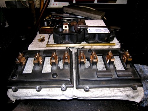
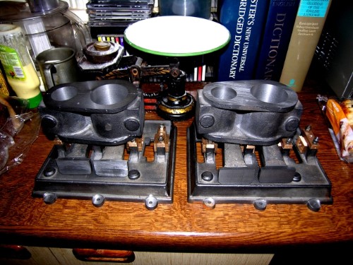
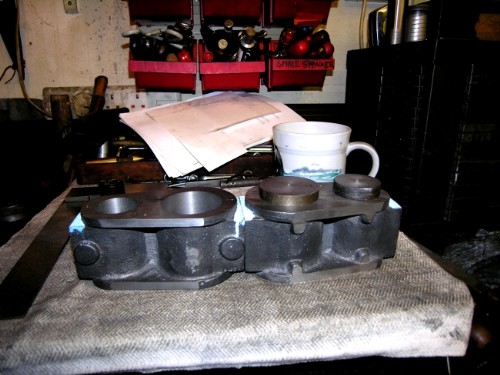
Close of play, both beds with the bearings and caps fitted and ready for the crankshafts. Then a search through the treasures for two pieces of MS, 10" x 3" for the shafts. No joy so it's a meaningful call to Terry at Gissings this morning. Plenty to be going on with. I had a look at the rabbit and decided that the first job was to square up the surfaces on the standards to make sure they stand with the slides vertical. I'll take care of the alignment of the cylinders with the CS centre when I mount them on the standards. No reason why the standards can't be fitted now. Then there is a lot of cleaning up on the blocks and machining the steam chest faces ready for valve making and fitting. Lots to do up there so no rush for the crankshafts.
I reckon we are about a third of the way towards running engines! Nice to see it coming together. It struck me yesterday that this sort of simple compound is exactly what used to be fitted in my favourite little steamers, the Clyde Puffers. Nice.....
Stanley Challenger Graham
Barlick View
stanley at barnoldswick.freeserve.co.uk  |
Stanley
Local Historian & Old Fart
36804 Posts
|
|
Posted - 22/08/2011 : 06:18
I have a call for help. At a later stage I'll need an Edward's Air pump and a small steam valve. I need castings or completed items. Does anyone know a source?
One other thing, I have a complete set of castings and instructions for a Hemingway universal dividing head designed by Thomas for the Myford lathe. I have no interest in making it as I have dividing tackle coming out of my ears! If anyone wants it they can become proud owner at a very reasonable price. See this LINK for a full description. £140, yours for £70 if you want it. Email me at the address below (replace the 'at' with @)
Stanley Challenger Graham
Barlick View
stanley at barnoldswick.freeserve.co.uk |
Stanley
Local Historian & Old Fart
36804 Posts
|
|
Posted - 22/08/2011 : 06:45
Just went for a furtle on the web and found Bolton Steam Models in Oz. They sell plans and castings for this engine. A$1,000 each! £630 a set. I am a man of wealth and substance in the community!
Stanley Challenger Graham
Barlick View
stanley at barnoldswick.freeserve.co.uk |
Stanley
Local Historian & Old Fart
36804 Posts
|
|
Posted - 22/08/2011 : 16:48
 Rang Terry this morning and two pieces of MS are on their way and he'll weigh in the brass turnings. So, with that out of the way I had a look at the standards. Not much to tell really, a re-sharpened milling cutter and some careful setting up and all the faces milled off to a good finish and right angles. Don't bother about the overall lenth too much, the main thing to watch is mill the one which is shortest overall in the rough state and do its partner to match. The drawing says 6" overall, mine finished up 1/32" above this. No problem because you'll make the con roods to suit and any discrepancy can be allowed for there. Rang Terry this morning and two pieces of MS are on their way and he'll weigh in the brass turnings. So, with that out of the way I had a look at the standards. Not much to tell really, a re-sharpened milling cutter and some careful setting up and all the faces milled off to a good finish and right angles. Don't bother about the overall lenth too much, the main thing to watch is mill the one which is shortest overall in the rough state and do its partner to match. The drawing says 6" overall, mine finished up 1/32" above this. No problem because you'll make the con roods to suit and any discrepancy can be allowed for there.
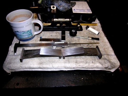 Close of play at noon. Two mating standards with the vertical guide face flat and polished ready for fitting the crossheads. Two more to do but that won't be tomorrow as I am being kidnapped and taken to Derbyshire. I shall call in at Masson Mill, deliver a Porter governor I have been guarding for years and have a look at the Jubilee Engine which is almost ready for commissioning. By the way, note the engineer's level, a good tool for making sure you have a level cut for the slide on the standard. Match that up with the reading off the bed and you have it square. A very sensitive level and I got it for almost nothing in a job lot. Always keep your eyes open! See you later on Wednesday! Close of play at noon. Two mating standards with the vertical guide face flat and polished ready for fitting the crossheads. Two more to do but that won't be tomorrow as I am being kidnapped and taken to Derbyshire. I shall call in at Masson Mill, deliver a Porter governor I have been guarding for years and have a look at the Jubilee Engine which is almost ready for commissioning. By the way, note the engineer's level, a good tool for making sure you have a level cut for the slide on the standard. Match that up with the reading off the bed and you have it square. A very sensitive level and I got it for almost nothing in a job lot. Always keep your eyes open! See you later on Wednesday!
Stanley Challenger Graham
Barlick View
stanley at barnoldswick.freeserve.co.uk |
Stanley
Local Historian & Old Fart
36804 Posts
|
|
Posted - 23/08/2011 : 05:06
All ready to be kidnapped and I found myself thinking. One of the nicest things about doing a job like these engines is that when you have a spare moment for thought you can review progress and the next steps, a lovely way to drop off to sleep at night! I got one of the standards and offered it up to the pad on the bed whuch got me to thinking about marking centre lines on the crosshead slide face, making matching marks on the bed on the CL of the cylinder and checking the distance between them, it should be 2 3/4" exactly.
This got me to thinking about whether the standards can be permanently mounted on the bed and if so, is there anything else that needs doing to them so they don't have to be taken off again. It led me to the conclusion that the best way to proceed is to mill flats on the backside of the standards for mounting the pivot pin for the air pump linkage and the brackets that will support the condenser. I can also make the crosshead slides and mount them on the guide flats. All fiddly work that will have to be done in the end and are better got out of the way now. There's another aspect of it, It means that the construction is growing from the bottom up which feels right. Nice! Pity I have to go off and enjoy myself today!
Stanley Challenger Graham
Barlick View
stanley at barnoldswick.freeserve.co.uk |
Stanley
Local Historian & Old Fart
36804 Posts
|
|
Posted - 24/08/2011 : 07:38
Tiring day yesterday so today is careful measuring and adjusting and thinking time. Could be some pics of the surface plate coming into play!
Stanley Challenger Graham
Barlick View
stanley at barnoldswick.freeserve.co.uk |
Stanley
Local Historian & Old Fart
36804 Posts
|
|
Posted - 24/08/2011 : 16:01
Had more energy than I thought. A full day's work.
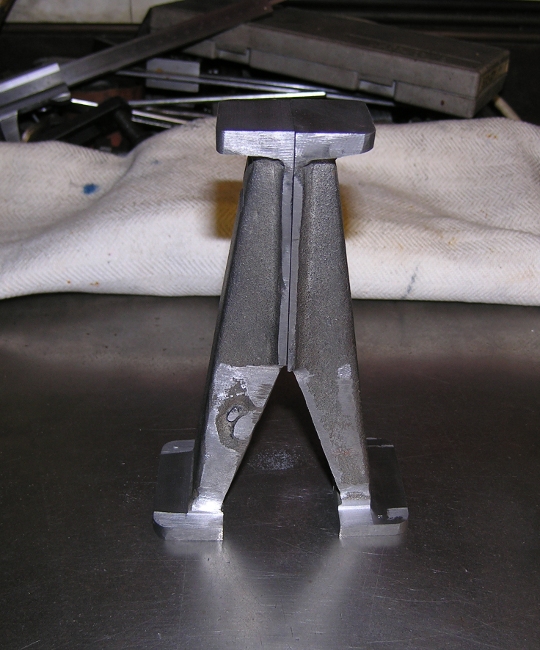
If your standards match up like this when stood flat and firm on the surface plate you're OK!
Close of play. All machining done, surfaces square and clean. Standards all numbered and corresponding numbers on the beds. All centre lines found and marked. I've machined the back side of two of the standards, the other two will be first job tomorrow. Then make and fit crosshead slides I think. Terry delivers steel for CShafts this afternoon, he had some 75mm bright bar going spare and I reckon I can make that do. If necessary I can reduce the stroke a touch. Cheating I know but what the hell, they aren't driving a ship!
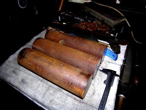
It's nice having friends you can call on. Terry has dropped the 75mm bar in, I asked for three in case I make a mistake! Over the years I have done a lot of work with Terry and I've never been greedy, I reckon that if you're dealing with the right sort of people it all levels itself up in the end. So the billets haven't cost me anything. Wonderful! It's 3/64ths under 3" so I'll lose 3/128ths off the stroke. I don't think the chief engineer will lose too much sleep over that!
Stanley Challenger Graham
Barlick View
stanley at barnoldswick.freeserve.co.uk |
Stanley
Local Historian & Old Fart
36804 Posts
|
|
Posted - 25/08/2011 : 06:56
Nothing to report yet today but I was thinking I need to clean the bottom ends of the crosshead guide surfaces so they look tidy when I fit the guides.
It's still dark and raining so I thought I'd have a word about crankshaft turning. The actual machanics will become clear when I start doing them and post the pics but I though a few general points might help some people.
If you read the old books on shed practice the classic method of turning shafts from solid on more than one centre is to do it between centres with a catch plate and a dog to transmit the drive to the shaft. The big problem for me is that there are a lot of interrupted cuts and the driver peg tends to bounce off the dog. Lots of weird methods for alleviating this usually involving tying them together with a piece of string or something similar. It never looked like good practice to me. I like something a bit more positive.
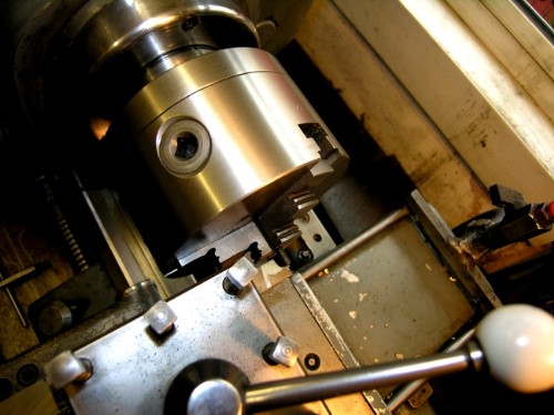
Best way I have found involves the use of the four jaw independent chuck. Big, gets a good hold and always remember that properly set up it's the most accurate chuck you own! You'll see that what I do when I've found my centres, marked them and drilled the biggest centre holes I can get away with. (Newton always said that the bigger the Slocombe drill the better!) I use the dead centre that fits into the mandrel of the lathe to engage the centre in the billet but reinforce this by carefully tightening the four jaw down onto the steel. Once you've set that up carefully you know you've got it by the short and curlies!
I used to cut everything with ordinary lathe tools but Newton put me right on that one. Mark out the lumps that have to be got rid of and mill them out, far quicker metal removal and cuts down on the interrupted cuts when you are finishing the crank journals. To give you an idea, the billet for the crankshaft on the big compound I made weighed 37lbs and the finished shaft weighed about seven pounds. It's a lot of swarf! I'll make it all clear when I get onto them.
You'll also find accounts of avoiding eccentric turning by making the shafts in sections and building them up. There are so many traps for the unwary in that I'd never even consider it. Mind you, having said that there's one place where you have to use a variant of this method and that's fixing the driving wheels on loco crankshafts. Newton always used to shrink the wheels on just the same as fitting the cranks onto steam engine flyshafts but I introduced him to shaft grade Loctite anaerobic glue! He was very suspicious at first but we did an experiment and I convinced him. He said it was an improvement because no matter how careful you were interference fits always drifted a bit when you were pressing them on. With Loctite you could get the relationship between the con rod pin on the wheel and the CS journal dead accurate. Nice to be able to teach the old lad something! He taught me plenty. By the way, if you ever have to dismantle something stuck together with Loctite just heat it up, this breaks the glue down.
I have a story for you about turning crankshafts out of the solid. Brown and Pickles used to make their own three throw feed pumps and the last one I know about is the one I installed at Bancroft Shed, it's still there in the cellar. The crankshafts were turned out of the solid on four centres from a billet of 90 ton steel, they tried forgings but they gave trouble so went back to the solid. When Jim Fort made the CS for the pump at Bancroft it took him about ten days turning. At one point he lost concentration and turned the collar off for locating the shaft in one of the end bearings. They had to cast a special bearing machined with the spacing collar on the bush instead of the shaft. If you ever go there have a close look and you'll see what Jim had to do to rescue the job. None of the shafts made out of the solid ever gave any trouble.
One word about Slocombe centre drills. I was at Harewood traction engine rally once and was rummaging on a stall selling interesting bits. There was a box full of Slocombe drills and they were £5 for ten. Dirt cheap but after a while the stall holder noticed I was picking my way through them and asked me what I was doing. I said I'd tell him after I'd bough then drills from him. Once I'd paid I pointed out that he had two types of drills in the box. One was the normal one with a definite junction between the pilot drill and the inclined face that gives you the bearing surface. There were also some where there was no junction, they were ground in a curve. These are high precision drills, the curved face automatically ensures that the centre is dead accurate in the hole, no lathe is perfectly centred, some are better than others but there is always a tiny discrepancy. I told him to look up the price of the HP drills! When I left him he was sorting through the box and dividing them up! Always keep your eyes open!
Right, it's almost daylight. Out into the rain with Jack and then back into a warm dry shed!
Stanley Challenger Graham
Barlick View
stanley at barnoldswick.freeserve.co.uk |
Stanley
Local Historian & Old Fart
36804 Posts
|
|
Posted - 26/08/2011 : 06:47
Day taken up by writing for BET so all I did was clean the bottom of the guide surfaces up. I shall mark the centres on the other engine and make the crosshead guide strips. Now where did I put that gauge steel.......
Stanley Challenger Graham
Barlick View
stanley at barnoldswick.freeserve.co.uk |
Stanley
Local Historian & Old Fart
36804 Posts
|
|
Posted - 26/08/2011 : 14:09
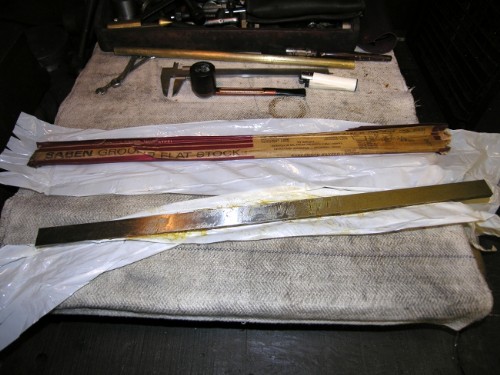
The ground flat tool steel stock was exactly where it should have been, neatly tucked away in the tresure chest. This is unhardened tool steel, tough but it machines cleanly with care.
One check I wanted to make was how the feet of the standards matched the pads on the bed when the guide faces were in line. The easiest way to do this is clamp a piece of ground tool stock to the faces and then offer them up to the pads. Not bad, only one pad slightly out of line so I marked that one up. No need to worry about the relation of the guides to the shaft because the final alignment will be made when the cylinders are mounted on the standards and the crossheads will be made to bring the piston rods over the centre line of the shaft.
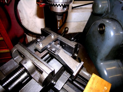
Milling the strips for the guides out 1/4". The plan is to slit the guides after drilling the holes for the 1/8" Whitworth set screws I shall use because they are old-fashioned ones with full hexagon heads, not the skimpy heads you get on modern bolts.
All the guides are milled out, matched to their standards and numbered. They are ready for marking out for 4 set screws down each side. Then they can be split and used as guides for marking the tapping holes in the castings. There will be less bearing surface on the top of the crosshead slide than in the original drawings because Bahrett allowed too much in my opinion. When the engine is running normally most of the bearing thrust is on the guide face not the retaining lip. The only time this changes is when the engine is in reverse and as this is only in short bursts doen't matter as much.
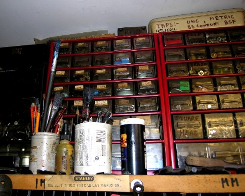
This set of drawers contains most of my small taps and dies. It's a good example of how you can build up stocks over the years. I doubt if you can think of a thread that I haven't taps and dies for including some fairly esoteric ones like the old Bicycle threads! An old mate of mine looked at it one day and reckoned there wouldn't be much change out of £2,000 if you went out and bought them all new today. Sounds a lot to me but I think he might be right. And no, I'm not going to search the net to add them up! I've got better things to do like mark the guides up for the clearance holes and slit and finish them. I want them mounted on the guides before I mount the standards. Onwards and upwards!
Stanley Challenger Graham
Barlick View
stanley at barnoldswick.freeserve.co.uk |
Stanley
Local Historian & Old Fart
36804 Posts
|
|
Posted - 28/08/2011 : 06:53

The finished blanks for the crosshead guides ready for marking up for the bolt holes and drilling with a clearance hole for 1/8" Whitworth set screws.
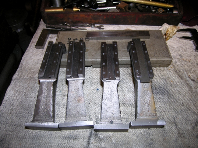
The guides are split and cleaned up, Blank strips the same size as the crosshead wiill be inserted and the next step is to clamp the assemblies in place on the standard and use the clearance holes as guides for drilling the tapping holes in the casting. I forgot to do a pic of this but will do one today as I carry on with the process.
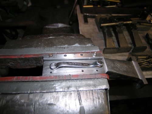
The first strip mounted on it's standard ready for drilling the odd hole that was missed because the clamp was in the way. No problem, the tapping hole can be drilled, the hole tapped and the set screw inserted without taking the strip off. I've checked the strip for alignment on the standard and it's OK. Now all I have to do is spend a long time carefully repeating the process for the other standards, carefully tapping the holes and fitting the strips, all in the right places so the numbers match. No rush with any of this, you need to keep your mind on the job and go slowly forward. A mistake at this point takes so much work to rectify it. Notice the nice bold heads on the old machine made set screws, I don't think you can get them these days. I got a lot of assorted nuts and bolts etc by buying old workshops up. Notice also the hexagon ring key that exactly fits the heads. Well worth spending money on good small spanners instead of buggering heads up with adjustables. Quietly away today....... See you later!
Stanley Challenger Graham
Barlick View
stanley at barnoldswick.freeserve.co.uk |
Invernahaille
|
Posted - 28/08/2011 : 13:13
Stanley,
Right tools to make a right job.
|
Stanley
Local Historian & Old Fart
36804 Posts
|
|
Posted - 29/08/2011 : 08:57
Never a truer word Robert. I've seen too much of these miracle workers with a hammer, a blunt chisel and a big parrotbill spanner. A bloke once asked me why I needed so many spanners when I was reconditioning diesels. I told him that a bad fitter needs lots of spanners in case he loses one....
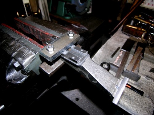
Here's the pic of the clamp that I promised you yesterday. It lets you make sure that the alignment and spacing of the guides is as good as you can get it. God knows I need all the help I can get! Rwo bits of srap and two 1/4" Whitworth bolts. In case you didn't know, Whitworth thread was designed specially to give the best hold for steel threads in cast iron. It's never been improved on and I stick with it! British Standard Fine was developed for steel on steel. One other little tip, a set screw in cast iron has maximum hold when the engaged thread length is 1 1/2 times the bolt diameter. In steel it is the bolt diameter. A rough guide but it works.
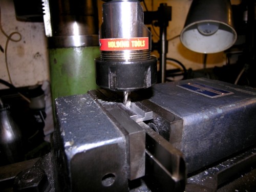
Still firmly held in the clamp and the end holes in each guide are drilled tapping size centrally through the clearance holes. Its a number 40 drill. Number drills are old-fashioned nowadays but were made to wire gauge which is the best tapping size for small screws.
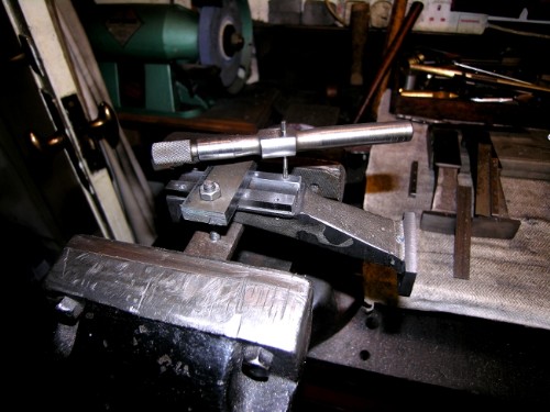
Still held firmly in the clamp, the end holes are tapped and the set screws fitted. Then the clamp can be taken off and the other four holes drilled and tapped through the clearance holes and the set screws fitted. I've made a fitted strip for each completed guide so that when I make the crossheads I have a gauge for each crosshead. The width varies a bit but they average at 5/8" x 1/8" thick and the gap is 7/16" so the bearing surface under the strips is 3/32" each side, plenty of hold, any more would look clunky. Some people just measure for the tapping holes, mark up and drill. They may be better at marking out than me. If the tap will go through the clearance hole the set screw will screw in with your fingers! Take your pick.....
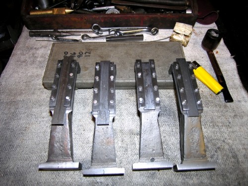
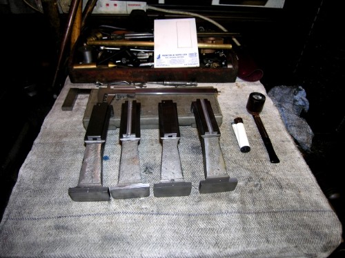
Four hours of careful work and at close of play we have four standards with crosshead guides fitted, all with a fitted strip as a guide for the width of the crosshead slide when I get to them. I only broke the tip of the tapping drill once when it was breaking through at the side of the standard, not bad. When you have a 1hp motor driving a number 40 drill the drill will give up first!
Apart from the nice warm glow seeing another step completed, I reflected on scales. These beds are 8 1/2" x 5" and the overall height will be about 9 1/2" . In my head this engine is a typical Puffer or small tug engine and if you scaled it up X12 this looks about the right size. 8x5 feet and 9ft high would be right. So we are looking at one inch to the foot. On this scale the guide bars are about 3 1/2" wide which is right. If you look at many model engines, particularly the Stuart designs the small parts like these bars are way out of scale and look clunky. Funnily enough, when Johnny Pickles made his wonderful cross compound mill engine (In Bradford Museum now and seized up because they ran it on compressed air and rusted the bores!) he made it one inch to the foot and told Newton afterwards that it was a mistake as small items like the rods in the valve gear were watchmaking and a pain in the neck. The nice thing about a simple engine like this is that the valve gear is a lot heavier and no problem at 1/12 scale.
We've reached a straight edge now and I have a choice where I go next. Funnily enough the decision came down to simple house-keeping. I think you may have realised I like things clean and tidy! Well, my scrap bin in the yard is half full of brass turnings and it won't get weighed in (courtesy of Terry Gissing) till after he comesback from holiday on September 12th. The one thing thbat is certain about crankshaft making from solid is that you make a lot of swarf and I want the bin empty so that I can have a quick clean up, stamp the swarf down in the bin and keep tidy.
So the decision is made for me, I shall attack the cylinders and associated bits, plenty to go at there! One other thing that has been on my mind. Nr Bahrett's design for the crosshead bearings is strictly as in the full size engine with adjustable crosshead pin bearings and separate shoes for the slippers. At the moment I'm favouring making the piston rods and crossheads in one piece with a bronze bush pressed in and reamed for the crosshead pin to the con rod. This is a small table engine not a working engine and it will be easier, more tidy and only the purists will object. Well, they aren't making it! I'm too old to be making work!
So the standards and guides look in scale and I'm satisfied with them. Now for some careful measuring on the cylinder block. First job is to get the steam chest faces right and ready for the chests, covers and valves. Then I'll do a bit of fancy milling tound the curved edges of the castings, not strictly necessary but looks so good when the head is finished. Onwards and upwards!
Stanley Challenger Graham
Barlick View
stanley at barnoldswick.freeserve.co.uk |
Stanley
Local Historian & Old Fart
36804 Posts
|
|
Posted - 30/08/2011 : 06:49
Mot a lot to record in pictures but a lot of careful thought went into the job yesterday. Before I started chopping lumps off the cylinder castings I though I'd better do some basic measuring and compare what the drawings from the ME said and how this transferred to the castings.
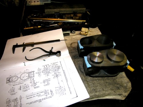
First thing I did was make sure I had the bore centres and centre lines accurate. I only know one way to be absolutely certain, make plugs for the bores with centre holes. My original centre lines were quite accurate and only needed slight revision. I need these to be able to mark both the steam chest faces dead parallel, I've seen some horrible mistakes made in this department and once done they can't be undone. I've put white marking fluid on the casting and was ready to mark the cuts.
However, I needed one more measurement, I needed to be certain that I cut the faces so that the centre line of the separate steam chest casting was in line with the apertures in the bed for the eccentrics to run in. You can always get out of trouble by offsetting the valve rod connection if you get into trouble but better if everything is in line. First thing I did was go to the coloured supplementary drawing from the ME and the dimensions on the drawings in the text. First problem was that the supplement design doesn't match the drawings and there are no specific measurements. So I shall face the steam chests, find the centre of the valve rod and use this to establish the correct position for the face on the cylinder block. It's a long way round I know but doesn't involve any extra machining and ensures I get it right.
The good news is that initial rough measurements indicate that the eccentrics can be aligned dead accurate with the cast apertures in the bed. Johnny got it right even if the ME didn't! Incidentally, the plug in the LP bore is CI and so could very easily become the piston. These plugs are going to come in useful for another purpose, locating the blocks for machining of the external faces on the block......
Stanley Challenger Graham
Barlick View
stanley at barnoldswick.freeserve.co.uk |
Stanley
Local Historian & Old Fart
36804 Posts
|
|
Posted - 31/08/2011 : 06:25
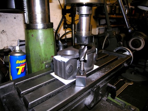
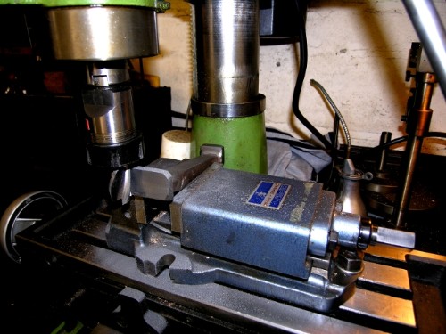
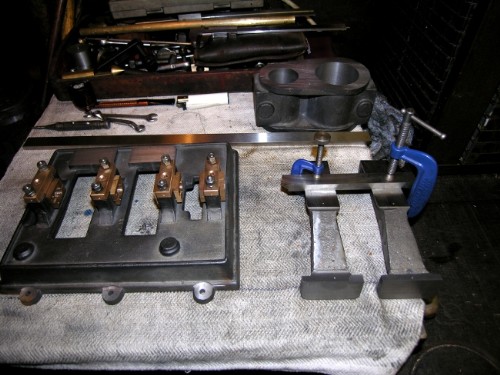
Cylinder block clamped down on the bed using the specialised fixture set. Bit of a luxury this, you can make your own but not as good or versatile as the purpose-made sets. First job is to mill the sides of the edges straight and clean.
All the sides milled straight. Now for the clever bit! Drill 3/8" holes in the two plugs and bring on the rotary table!
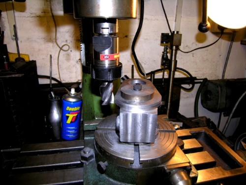
Remember what Robert said about tools for the job? Here's the rotary table, a very useful piece of tackle. Clamping the block down central using the plug means that once the table is set up in the right position, you can rotate the casting against the milling cutter and get a dead accurate circular cut round the end of the block at a depth deep enough to clean up the top side of the valve chest base as well. There's no other way I know of doing this job, making an interrupted circular cut. The table can also be used for drilling hole on a pitch circle, say for stud holes in the blocks or the lids. It will also come in handy for milling the bottom lids of the cylinders which have a projection on the side to match the tops of the standards and which is used for attaching the block. We'll come to that later. Mind you, because I have two ornamental turning lathes with built in tangential dividing gear I can go at this into drilling on pitch circles in more than one way. I might have a play and treat you to more than one route to this so you can decide which way you want to go. One thing is certain, the use of dividing gear is far more accurate than marking on a PCD and drilling. We'll come to that later.
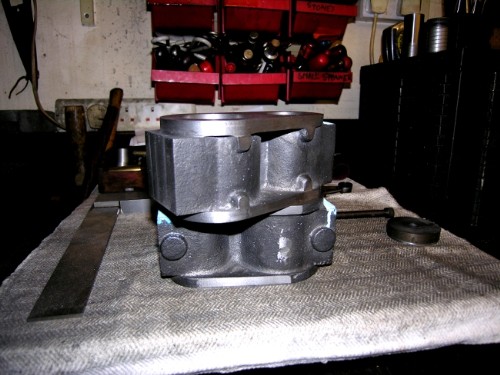
Close of play at noon yesterday. The LP end of one of the blocks is tidied up and looks as though someone cared! Today will be careful milling of the other LP end and both the HPs. I use a smooth file to clean up any minor discrepancies in the transition from the straight sides to the curve. I'll touch the milling cutter up on the Clarkson grinder before I start. Going back to Robert again, one of the advantages of being old is that over the years you acquire the right tools for the job. There is no way anyone can hand grind milling cutters accurately to the standard you can get with the Clarkson. If you keep your eyes open you can get these tools secondhand at very reasonable prices because most people don't know they exist. By the way, the last job will be milling the bosses on the casting off clean and level. On finish, Ilike the contrast between the clean grey casting and the machined parts and don't like to see them painted. Besides, to paint a model properly you need to dismantle them. I'm too old to be doing that!
Right, off for a walk and then back into the serene atmosphere of the shed. No political troubles or recession in there, just old-fashioned honest endeavour!
Stanley Challenger Graham
Barlick View
stanley at barnoldswick.freeserve.co.uk |
|
|
|
|