| Author |
 Topic Topic  |
|
Stanley
Local Historian & Old Fart


36804 Posts

|
|
 Posted -
25/11/2004
:
14:20 Posted -
25/11/2004
:
14:20
|
I've always been fascinated by the things people do in their spare time when they can do exactly what they want to do. Men and sheds are a particularly fertile field. Women tend to do their thing in the comfort of the house.
I was delighted to see Andy's picture of the clock movement he has made.
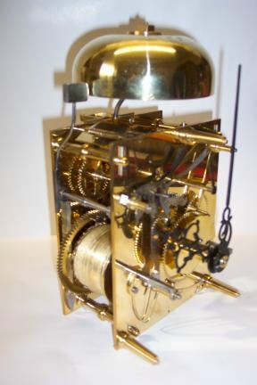
It struck me that we could perhaps start a new topic devoted to spare time skill. So Andy starts it off and my contribution is this:
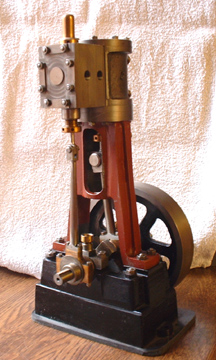
It's a small steam engine made from scratch and is based on the Stuart 5A but a longer stroke. One of these will drive a 14 foot boat with steam at 250psi. By the way, we don't like to call them models, it's exactly the same construction and materials as a full size engine, just smaller. So come on out there, let's hear about what you make in your spare time. I reckon we could be in for some surprises!
Stanley Challenger Graham

Barlick View
stanley at barnoldswick.freeserve.co.uk
|
|
| Replies |
| Author |
|
|
Stanley
Local Historian & Old Fart
36804 Posts
|
|
Posted - 15/02/2007 : 16:17
Walking up Letcliffe and thinking about Johnny and the dividing head it struck me that if he had found out by experiment that the combination of worm, gear and divisions on the plate which he had used on the last version of the tangential gear on the 1927 lathe was best he might have done exacly the same thing on the 1956 lathe. So I went and had a look, sure enough, the large wormgear cum dividing plate in the headstock of the 1956 lathe is 180 teethX9TPI. I worked this out in exactly the same way as I did for the 1927 lathe and came to 6.36" PCD with an allowance for depth which added .36" to the blank diameter which is 6.625". Making a proportionate allowance for 12TPI I have decided on 4.97" for the blank. Looking again at the 1956 lathe the divisions on the front of the plate are 30, 28 and 27. The plate can be reversed and the divisions on the other side are 79, 26, 19 and 8. I'll make a guess that using these divisions you can divide a circle into just about any number you could possibly want.
So, I'll do my own experiment now. I have a small blank disc and I've done the same calculation and allowance on it and have come up with a 75 teeth worm gear which needs a blank 2.19" diameter. I'll bore it the same size as the mandrel of the 1927 lathe so that if it is successful it will be a spare gear. Either that or I'll cut it as a straight gear and use it as one of the gears for screwcutting. Whatever, it won't be wasted, even if it only ever gets used as an idler. Isn't it exciting!
Stanley Challenger Graham
Barlick View
stanley at barnoldswick.freeserve.co.uk  |
Stanley
Local Historian & Old Fart
36804 Posts
|
|
Posted - 17/02/2007 : 07:13
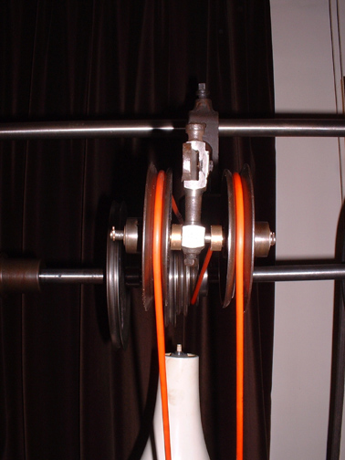
I didn't have a lot of time yesterday as Friday is shopping day and I needed to do an article for the BET to keep a cushion in the stockpile. So I didn't attack the worm but tackled an annoying rattle in the jockey wheels on the overhead gear. The original spindle was OK but the wheels were a very slack fit and the holes in the brass bushes of the CI wheels were different sizes at each end! So I put a piece of 3/16 silver steel in for a shaft and bored the wheels to fit. I put it back on and though better, the displacement of the belt due to the angle on to the driving pulley was dragging the wheels into the centre and they were rubbing on the central casting on the left side and on the square head set screw that secures the jockey bracket casting to the counterweight arm on the right. So, off again and two 1/4 inch wide bronze bushes in as spacers and I swapped the square head set screw for a socket screw ground down to reduce the size of the head. Runs like silk now..... Notice how the inside flange on the CI jockey wheels is cut down to avoid friction on the drive rope. The plastic drive rope is fine but I will try the 1/4 leather rope when it has soaked enough.

This is the set up. I realised last night that the supporting bracket that fits on top of the lathe bed could be set at an angle from the right side of the bed and this actually gives more room for adjustment. There's an advantage in having the saddle mounted on the front of the bed that I hadn't realised before. A bit of wear or bruising on the top faces doesn't affect the accuracy of the lathe. The more I work on this gem the more I realise what an amazing bit of kit it is. I remembered something that Newton once told me about this lathe. I have an idea that Newton once told me that the headstock bearings are tapered and made of hardened steel running on the hardened mandrel. Steel on steel is an unusual combination for a bearing but Johnny evidentlay thought it would be OK because being a small lathe, there are no heavy loadings.
Stanley Challenger Graham
Barlick View
stanley at barnoldswick.freeserve.co.uk |
Stanley
Local Historian & Old Fart
36804 Posts
|
|
Posted - 17/02/2007 : 11:08
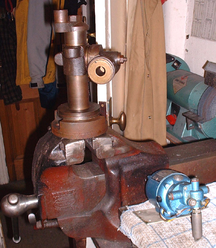
Right, what's he up to now! I think Johnny's ghost must be egging me on because I gave a lot of thought to how I could make a jury rig on the Harrison lathe to do the hobbing of the worm wheels but then decided this wasn't good enough. I knew I had this partially finished Potts type milling head in the treasure box and so I've dug it out. I want to make a proper hobbing and gear cutting setup that fits onto the vertical miller. I can hold the hob in the chuck and arrange a foot bearing for it. This gives me a rigid cutter. The milling head can be adapted to take mandrels to hold the blank and the rise and fall will enable me to adjust the cut for different blank sizes, the cross feed on the milling table will give me control of cutting depth and if all else fails, I can drive the hob by hand to get a very slow speed. I've never done this before and have no idea what spindle speed will work. I can get down to 140RPM on the mill and this would be less than 1rpm on a 180 tooth wheel. Sounds feasible to me. The little electric motor is a fractional gear drive motor that originally came off a large blueprint making machine. From what I can make out, one of the problems with free hobbing is drag on the cutter that can throw the divisions out. My idea is to either have a weight on a piece of drive rope putting pressure on the blank to cancel the drag or, a bit more complicated, have the geared motor driving a rope which slips on a driving pulley on the mandrel. I'll experiment before deciding on this. It would be a lot easier if Johnny would break silence! As it is, I need to work it all out by experiment. The beauty of doing it this way is that once I get the seup right, I am fit up for some serious worm wheel making in an accurate setup. One thing is certain, it will be fun finding out!
Stanley Challenger Graham
Barlick View
stanley at barnoldswick.freeserve.co.uk |
Stanley
Local Historian & Old Fart
36804 Posts
|
|
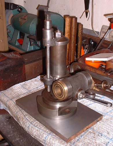
Posted - 18/02/2007 : 06:46
The first stage in any reclamation is always a good clean-up. Amazing what you learn by getting the muck off. The hosing for the mandrel has a taper at the business end, one of Johnny's favourite ploys for making a bearing with no end float. Complicates the making of the mandrel but a good thing. The base is marked with 90 degrees of division which will be handy for adjusting the angle of cut in certain circumstances like gashing or making skew gears. The original threaded rod that held it together is just that, a piece of 1/2 inch threaded rod I had handy when I was matching all the loose parts together so they didn't get lost. It offends me and is slightly short so the piece of 1/2 inch stainless is going to be the new one. That's the first job this morning. Then a few decisions about the barrel. I don't need the mandrel casting to rotate so I'm going to follow Johnny and cut a keyway down it and a matching peg in the housing. We also need an elevating screw fitting. Plenty to pass a quiet Sunday away I think! Onward and upward. I'm thinking forwards a bit and I think the favourite for a workholder is to follow Johnny's lead and put a threaded nose on the mandrel which will take the chucks off the 1927 lathe. I can rough turn blanks on the Harrison, Finish them on the 1927 and cut the gears on the miller. That way they should be concentric.
Stanley Challenger Graham
Barlick View
stanley at barnoldswick.freeserve.co.uk |
Stanley
Local Historian & Old Fart
36804 Posts
|
|
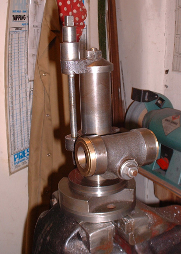
Posted - 18/02/2007 : 17:25
We've got a screw to regulate the rise and fall now..... And a new centre bolt holding it all together.
Stanley Challenger Graham
Barlick View
stanley at barnoldswick.freeserve.co.uk |
Stanley
Local Historian & Old Fart
36804 Posts
|
|
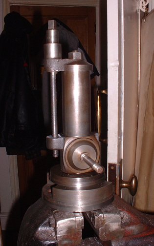
Posted - 19/02/2007 : 18:10
We're getting there. The keyway is cut and located by an Allen screw with a shaped end so it can come out of gear if needed. There is a lock stud fitted which bears on a brass plug and this locks the Mandrel housing to the pillar. There is a sigot on the bottom of the casting so that it can swivel to different angles. We need a base......
Out with the big four jaw and a bit of facing and boring. Marvellous what is in the treasure boxes!
Snug fit on the base, all we need now is circular slots milling in the base to give 90 degrees movement and some holes drilling in the base to match the slots on the beds of both milling machines. Plenty of weft for tomorrow.......
Stanley Challenger Graham
Barlick View
stanley at barnoldswick.freeserve.co.uk |
Stanley
Local Historian & Old Fart
36804 Posts
|
|
Posted - 20/02/2007 : 09:33
Just had me breakfast and sat thinking about the job. It dawned on me that I have made a fundamental error in thinking that I could use the vertical mill. If I do I'll have to make provision for an adjustable foot bearing for the hob because it will have to go on the table and moving the table will be the way to increase depth of cut. All possible of course but too much trouble so I went and had a look at the Harrison Mill. First thing is that I can get a cutting speed of 67rpm on it. Second thing is that in the days when I was in funds I spent an incredible amount of money on an ETM chuck and holding system for the vertical mill. It's the best way to hold cutters, absolutely rock solid. While I was getting the kit I got talking to the salesman and he persuaded me to get one to fit the Harrison mill. Ridiculous price but the same collets fit both so I bit the bullet. I have never used it! But now, it comes into its own as it is the perfect way to hold the hob horizontal over the table and so I'll have complete freedom of adjustment of cut. All I need to make is a bush for the tail bearing on the milling spindle that will take the free end of the hob. I'm glad I thought of this now as it means I know exactly how to orientate the Potts stand on the base plate and the table. Nowt like a quiet think every now and again!
One thing that strikes me is that you may think I'm going to lot of trouble with this but once it's done it's sat there on the shelf ready for a gear-cutting job in a matter of moments. One thing I have is plenty of time, no gaffer egging me on to make progress. Worth the effort and very satisfying.
Stanley Challenger Graham
Barlick View
stanley at barnoldswick.freeserve.co.uk |
Stanley
Local Historian & Old Fart
36804 Posts
|
|
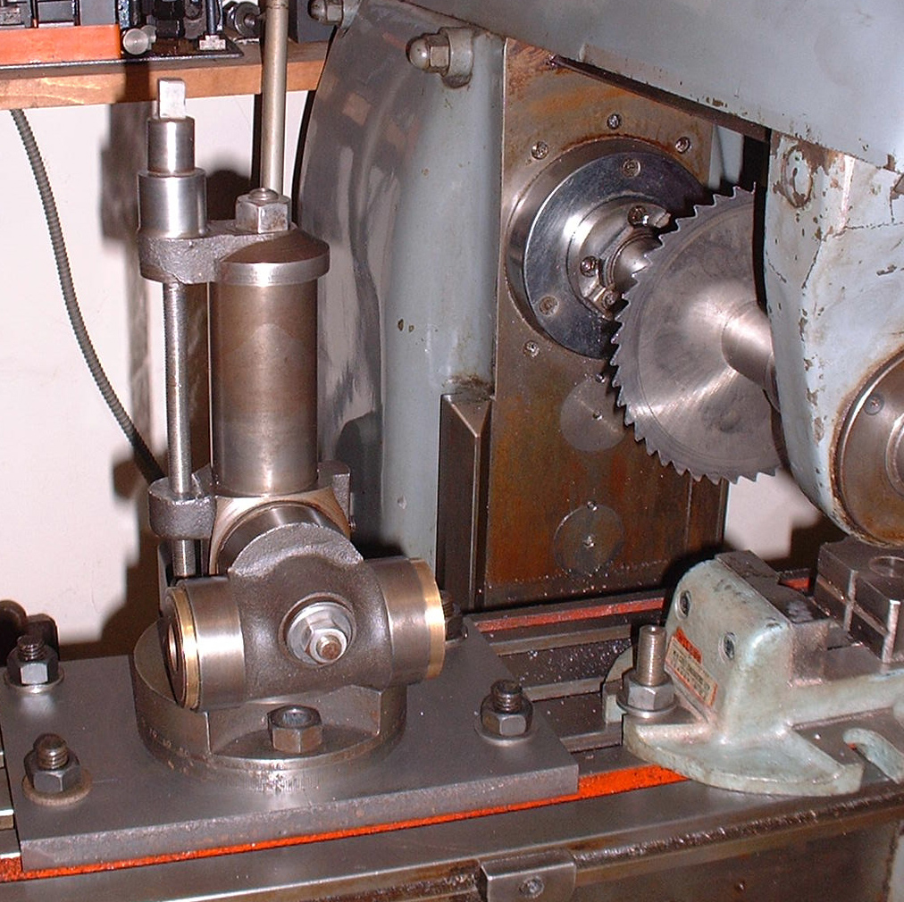
Posted - 20/02/2007 : 18:08
The piece of plate is good stuff, boiler quality, but it's tough stuff. A bit of serious slotting using the turntable. A very useful bit of kit to have about. You can see the ETM chuck here, mate to the one for the Harrison. Never known it loosen its grip.
Stanley Challenger Graham
Barlick View
stanley at barnoldswick.freeserve.co.uk |
Stanley
Local Historian & Old Fart
36804 Posts
|
|
Posted - 21/02/2007 : 06:10
If you look in the right background of the pic above you'll see a small grinding wheel on the Clarkson T&C grinder. I think I'll be a good boy this morning and sharpen the cutter before I do the second cut. Not much point having the tackle and ploughing on with a dull cutter.... Only five minutes of a job because it is set up for the type of cutter I am using.
Stanley Challenger Graham
Barlick View
stanley at barnoldswick.freeserve.co.uk |
Stanley
Local Historian & Old Fart
36804 Posts
|
|
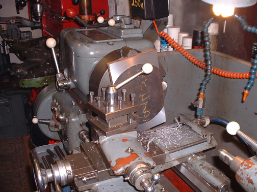
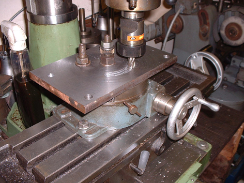
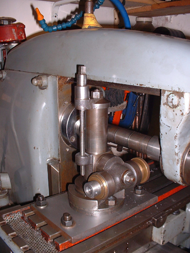
Posted - 21/02/2007 : 12:55
Right,we're getting somewhere now. The head is mounted on its base plate and here it is on the bed of the Harrison miller. What we need now is a mandrel........ I've gone off the idea of fitting the chuck on, I have decided to keep it simple and have as little overhang as possible. I'm going to mount the blank directly onto the end of the mandrel and worry about coping with different sizes of bore when I come to it. Just for the moment I'll make it to fit the 1927 lathe gears because they are the ones that will get done first.
Stanley Challenger Graham
Barlick View
stanley at barnoldswick.freeserve.co.uk |
Stanley
Local Historian & Old Fart
36804 Posts
|
|
Posted - 22/02/2007 : 07:22
I re-oriented the column on the Potts type head so that the vertical adjustment didn't interfere with the miller.
Stanley Challenger Graham
Barlick View
stanley at barnoldswick.freeserve.co.uk |
Stanley
Local Historian & Old Fart
36804 Posts
|
|
Posted - 23/02/2007 : 05:37
The spindle is nearly finished..... How come I can never measure tapers accurately? I measured it at seventeen and a half degrees. I eventually got a perfect fit, lapped in, at 15 degrees. First job today is finishing this off....
Stanley Challenger Graham
Barlick View
stanley at barnoldswick.freeserve.co.uk |
Stanley
Local Historian & Old Fart
36804 Posts
|
|
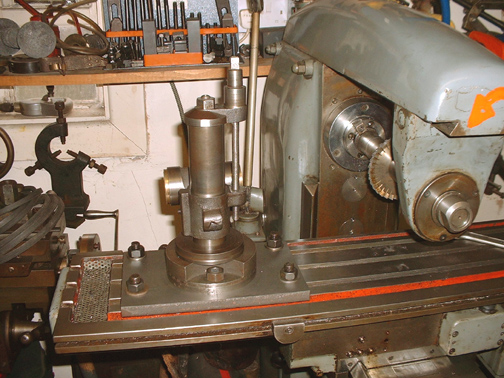
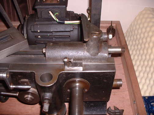
Posted - 24/02/2007 : 12:22
Right! The head is finished and here it is in place under the spindle with a brass blank in ready for a practice. What I need to do now is take the mandrel out, substitute the milling chuck and arrange a tail bearing for the hob. This would be easy if I could walk round the back of the miller to get to the draw-bolt that holds the mandrel in place. As it is I shall have to do a bit of climbing! I'll have a look at that this afternoon, it's raining and I feel like a zizz......
Stanley Challenger Graham
Barlick View
stanley at barnoldswick.freeserve.co.uk |
Stanley
Local Historian & Old Fart
36804 Posts
|
|
Posted - 25/02/2007 : 07:18
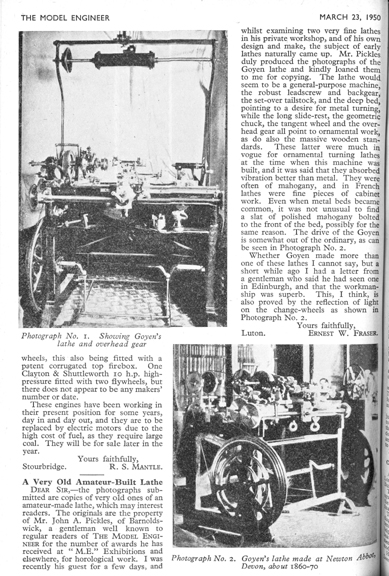
I didn't go back in the shed yesterday after I had a sleep. I went and did a bit of digging. This is one thing I found in my run of Model Engineers from March 1950. I hope you can read the letter. What interests me is that Mr Fraser mentions Johnny showing him two lathes 'of his own design and make'. This was in March 1950. I have always described the large (12" swing) OT lathe that Johnny built as the '1956 lathe' because I am certain I have seen that date stamped on it somewhere. I can't find it at the moment and am beginning to think that Johnny built the lathe earlier. I have seen pics of it with different configurations of drive and feedscrew arrangement and it could well be that 1956 is the date of the lathe in its present form but that it was built earlier.
I found the reference to the ME article on the website of the Society of Ornamental Turners and on the same site there was a very good article by a bloke called John Edwards which is well illustrated and gave me some more valuable clues about some of the bits in me treasures that I hadn't positively identified. I'm going to have to suspend worm wheel operations and do a thorough trawl of the treasures because I know I have some of the more esoteric accessories buried in there. What a good job I kept faith with Johnny and never threw anything away....... One nice quote I found in the search of the ME was about a man who purchased a very expensive OT lathe to serve his new hobby. He turned an oval cigarrete box and lid and as a final complication, spent a lot of time cutting a screw thread on the body and the lid. He was quite dismayed when he found the lid wouldn't screw on! You live and learn!
Stanley Challenger Graham
Barlick View
stanley at barnoldswick.freeserve.co.uk |
Stanley
Local Historian & Old Fart
36804 Posts
|
|
Posted - 25/02/2007 : 12:49
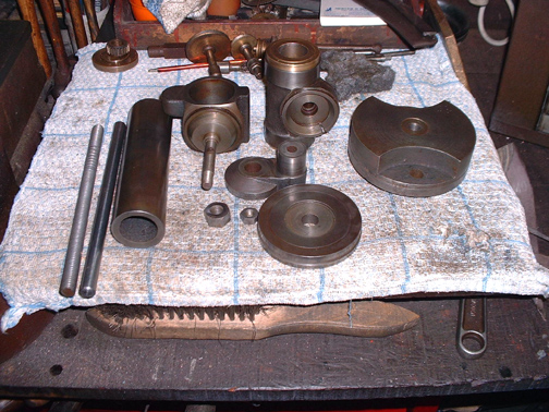
It's been a productive furtle.....
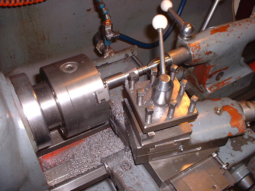
The 1927 lathe has gained another accessory, a hand turning rest. It is set here for working on the face but can be swivelled round to work longitudinally as well. The spindle is turned eccentric and so it can be locked with a quarter turn of the square head on the end.
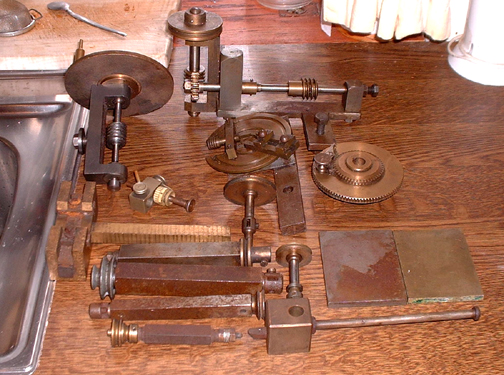
Here's an intersting group of accessories. Starting at the top, left to right: a dividing head, less worm, for mounting on the mandrel end of the 1927 lathe. Johnny turned out items like this as he needed them, he was such a fast worker. The next is a drive with two worm reductions in it for transferring drive from the overhead gear to a shaft. I have an idea that this was made by Johnny for driving the feedscrew on the 12 inch lathe when the headstock was locked for dividing, possibly for getting traverse on a gear cutter. Nesting into this below is a crafty little attachemnet for turning balls freehand, I doubt if it would be used for metals, although it's possible. Most likely for softer materials like ivory or wood. To the right of this is an indexable worm wheel. It's the same bore as the change wheels on the 1927 lathe but I havent worked out what it was used for yet. Go back to the left and the small object with the ivory index register is a stop for something. It looks like Holzapfel or similar to me. No idea what it was used with. The wheel on a shaft to the right of this is a spindle for a cutting frame. The four square bars are internal cutting spindles and there is another spindle for a cutting frame next to them. The two rectangular plates, one Cast Iron and the other Brass have been bothering me for a while because I knew i knew what they were but couldn't for the life of me thing what. It came to me this morning. They are sharpening plates for use with a goniostat which was a compound grinding gauge for sharpening ivory cutters. The cast iron plate was used with abrasive oil for initial sharpening and the brass pate was used with something like jeweller's rouge to put the final polish on the tool edge. The last item is for turning a circular recess in the end of a piece of material. A good morning sort out.
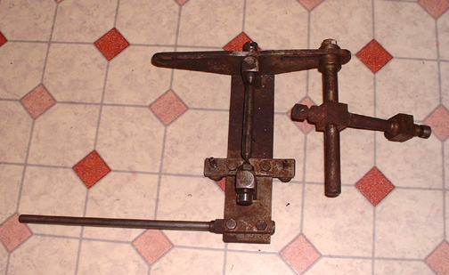
This one is a mystery. It's got a cutting spindle in it, two stops and an indent blade on the swinging arm. No idea what it was used for but I have no doubt it will eventually reveal itself....
Stanley Challenger Graham
Barlick View
stanley at barnoldswick.freeserve.co.uk |