| Author |
 Topic Topic  |
|
Stanley
Local Historian & Old Fart


36804 Posts

|
|
 Posted -
29/07/2011
:
06:27 Posted -
29/07/2011
:
06:27
|
New start as old topic was getting too big. Here's the LINK for the original topic.
Sheds are centres of honest endeavour and sanity, rare things these days. Please join in and tell us what you are doing in your shed. All are welcome!
[By the way, if I occasionally seem to be stating the bleeding obvious, it's because I'm aware of the fact that not everybody has the same experience so please forgive me.]
Stanley Challenger Graham

Barlick View
stanley at barnoldswick.freeserve.co.uk
|
|
| Replies |
| Author |
|
|
Stanley
Local Historian & Old Fart
36804 Posts
|
|
Posted - 16/10/2011 : 05:49
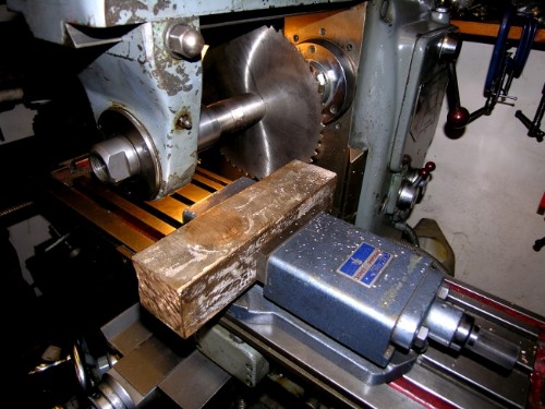
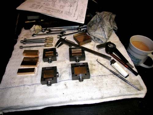
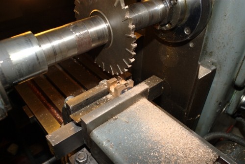
A good start on the valve blocks, a big lump of bronze and a slitting saw. The HM is worth house room if only for the time and effort saved in sawing stuff up!
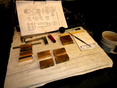
Almost close of play. Blocks of bronze ready for reducing to four valves and four driving saddles. I went on to sharpen a milling cutter and mill them all square for marking up. No need to worry too much about finish, just get on with it. The only fine finish is the valve face and that will be the last job, grinding them to a seal on the old surface plate. I've ditched Bahrett's valves, he hadn't met Newton! The blocks will be cut to a size that fits easily in the valve chest, a narrow slot milled right through to accept the valve rod and a broader cross slot cut to take a transverse block which will be the driver. This block is drilled and tapped to accept the valve rod which is threaded in the appropriate place 26TPI. The valve rod screws through the driver and needs no lock nuts or nipping bolts, it can't go anywhere. The big advantage of this arrangement is that you can fine tune the centering of the valve on the stroke simply by turning the valve rod and of course this doesn't need removal of the steam chest lid. Half a turn on the valve rod moves the block 1/52", .019", fine enough for anyone. We aren't driving 1000 looms!
Another thing I don't like about the old-fashioned way of making valve blocks is that they always seem to made as small as possible, not sure why, saving valuable bronze or giving plenty of room in the chest for steam passage? The bigger the bearing surface on the face, the greater the force exerted by the differential in pressure inside the valve and the steam in the chest and the better the seal. As for steam space, remember that the choke point for steam is the size of the steam port under the valve. As long as the area for passage of steam in the chest between the valve and the internal faces of the steam chest is greater there is no problem. Attention to steam flow in high performance steam engines like locos is a different matter and we aren't into that complication here. You'd be surprised how small the steam admission orifice is in a cylindrical valve used with Corliss Motion when a full sized engine is running on short cut off.
Worth mentioning here that the first time I realised this was when I was adjusting the valves on a three throw pump. Newton told me that 1/16" lift was ample on a big mushroom valve and sometimes in bad conditions you could get better performance with even less. As he said, make a saw cut in the side of a bucket and watch how fast the water runs out! He was right, big orifices aren't needed for large flows. Same applies to steam valves. End of lecture!
Stanley Challenger Graham
Barlick View
stanley at barnoldswick.freeserve.co.uk  |
Invernahaille
|
Posted - 16/10/2011 : 12:58
Its coming along nicely Stanley.
Your experience with the steam engines is paying you dividends.
The term engineer in its truest form means a person who drives engines. How many years did you drive the mill engines at Bancroft? You have probably been asked that question hundreds of times.
I think that is what puts you in good stead with your machining activity on your project.
This goes there, and if I do this, how will it effect that?
Just logical engineering process.
Where is the Jubillee engine housed Stanley?
|
Stanley
Local Historian & Old Fart
36804 Posts
|
|
Posted - 17/10/2011 : 05:23
Robert, six years at Bancroft running the engine and then eight years at Ellenroad getting that going again and dismantling and re-installing the Whitelees beam engine. I had a lot of valuable advice from good men and listened to them! Jubilee is in Masson Mill at Matlock Bath and I'll report when it is ready for regular visits. It's on the visitor's tour now as a work in progress.
Like many features on steam engines valves are interesting. Once you recognise the complications introduced by the angularity of con rods and valve rods and the consequent variations in stroke, piston speed etc. you start to realise that the seemingly simple slide valve is incredibly complicated. I once came across a reference and never noted it down, (I shall come across it again one of these days) The chief engineer of one of the main line railways was making a speech at his retirement dinner and he said that it was a shame he was going because after 50 years he thought he was getting somewhere near to understanding how the simple slide valve worked! There are more valve designs and motions than you can poke a stick at and they were all attempts to improve on the simple slide valve. The most successful stationary engine valve until the arrival of the drop valve was the cylindrical valve controlled by Corliss motion making variable cut-off easily possible. Funny thing about it is that the cylindrical valve is quite simply a flat slide valve rolled into a circle and fitted in a bore with a slot. Newton and I spent hours talking about the settings and both of us adhered to the practice of giving them as little cover as possible. Big subject but it was the key to getting the smoothest running.
Close of play yesterday and you could well ask what progress has been made.... There is a story, real life intervened! I went to make my early morning brew and the electric kettle didn't work! Get the old kettle on the hob and after the usual chores get the multi-meter out and do some tests.
The meter didn't work because I had left a battery in it and had the green lurgi and corroded wires. An hour spent cleaning up and re-soldering but no joy so into the bin and get no. 2 meter out. This worked and fault isolated to switch which was irrepairable so into bin with kettle on the grounds there was no point paying for an expensive repair on an old kettle, a new one will be cheaper in the long run.
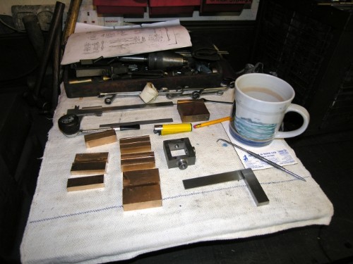
So, 90 minutes wasted! Yesterday was finishing squaring the blanks for the valves, much easier to do accurate measuring once this is done. Then some measuring up of steam chests and decisions about sizes. I am now ready to make accurate blanks and can start machining. However, I think my first job will be making the valve rods because I want to do some accurate measurements of them in position to determine the slot in the valve. They have to be done and better to make them now than later. So we start on the motion work!
One last thing about making engines. I've always said that you can read as many books as you like, and run engines for many years but you don't really understand the finer points of engines until you build them. I learned more about beam engines when re-building the Whitelees than from all the books. You are following the old fitters and you find all their mistakes. Making small engines is a similar process. You are doing exactly what the old fitters did to build a full size engine and you learn things about them that are never written down. I had a similar experience when refurbishing Johnny's lathes, I learned a hell of a lot about him from following his work. Fascinating stuff and the deeper you go, the more aware you are of your ignorance! Ah well......
Stanley Challenger Graham
Barlick View
stanley at barnoldswick.freeserve.co.uk |
Stanley
Local Historian & Old Fart
36804 Posts
|
|
Posted - 18/10/2011 : 06:31
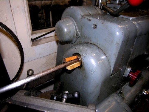
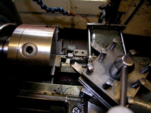
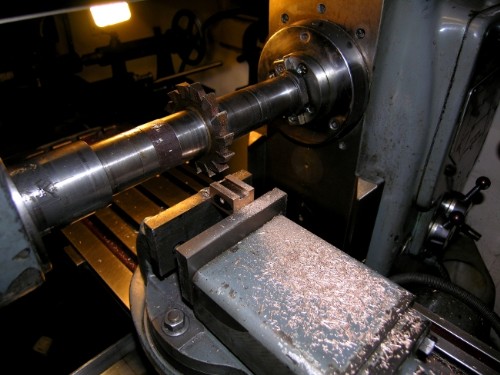
Funny pic to start with but first job this morning was to find a bar of 1/2" MS. One of the problems when running with a long bar through the mandrel is it wags about. A couple of wooden wedges can cure it.
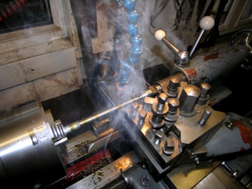
Cutting MS at high rates needs some coolant. I use neat cutting oil from a tank above the lathe and return it manually when the tank in the lathe bed is full. So, the flexible oil pipe fitted, a heavy cut relative to the size of the bar and away we go! This was a bit too heavy actually as you can see from the smoke! I went a bit steadier. I don't like to see the swarf turning blue as it peels off. Mind you, that never bothered Newton when he was doing big jobs. I once watched him making a heavy cut to true the tyre on a Black Five driving axle and the swarf was peeling off blue over his shoulder.
Notice the flexible oil pipe, best I have ever found.
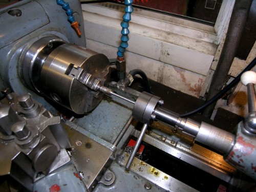
I have a bone to pick with you lot! You're supposed to be keeping an eye on me but nobody picked up my mistake when I said I was going to thread the valve rod 3/16" 26TPI. I was talking nonsense, the size doesn't exist. I was checking yesterday and realised my mistake, it is now 3/16" BSF which is 40TPI and therefore an even finer adjustment, .025 for every half turn of the valve rod. I find the tailstock die-holder essential, try as I may I can't thread fine stuff like this manually and often fail when doing long threads with a screwcutting tool in the lathe, I finish up with drunken threads. The die-holder cures this, a good thread every time.
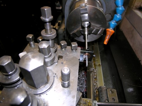
The rods need cutting back to just over 1/8" before threading and on fine work like this it can be a problem. A properly equipped lathe has fixed and travelling steadies of course but they are to big for this job so I brought out one of my 'get out of gaol free' gizmos. If you look carefully it is a little fixture that has a half inch brass bush drilled to 3/16" in this case but you can make them any size you want. There is a small cutter mounted so that you can set it to the finished size you want and once mounted on centre you just wind it forward into the cut on auto, dead simple and foolproof once set up. (Even for an old fool like me) They don't cost much and are a life saver.
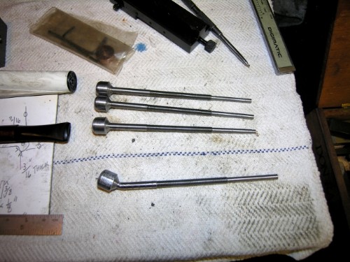
Close of play and we have two rods finished to the stage where they just need the eye putting on the end to take the fork of the valve rod. Bahrett had it the other way round, the fork on the valve rod itself but I don't like this. I was going to give you a treat and use the ball-turning tool on the end of the rod but it is too light to take the cut so I'll do it by hand after milling the flats on them. Doesn't look a lot for the morning but I had a lot of fiddling to do to get set up for the job. One item was having a good clean down and while I was at it I oiled all the lubrication points on the machines in the workshop. Easy to forget but a good thing every now and then. I rang Terry and asked for my swarf bin back! He's weighed the brass in but no bin as yet. I am going to need it!
Valve rods to finish today and once they are done I'm ready for the valves.....
Stanley Challenger Graham
Barlick View
stanley at barnoldswick.freeserve.co.uk |
Gugger
|
Posted - 18/10/2011 : 19:20
Stanley,
Why do you not use stainless steel for the rods?
Walter
|
Stanley
Local Historian & Old Fart
36804 Posts
|
|
Posted - 19/10/2011 : 07:10
Walter. Because I haven't got any and the old engines were all mild steel. Never seen an engine with SS rods. Less stuff I have to buy the better!
By the way, a small correction. The thread on the rods is 3/16" Model Engineer, not BSF. This is 40TPI so an even finer adjustment for one half turn of the rod.
Four blank rods made. Form tool used for rounding the end before milling flat and drilling for the hardened pin to the eccentric rod. However, Form tools are tricky little beasts especially when the shank in the chuck is only 3/16".....
See what I mean? I have to admit that when it grabbed there was a short burst of primal scream therapy and some extemely bad language!
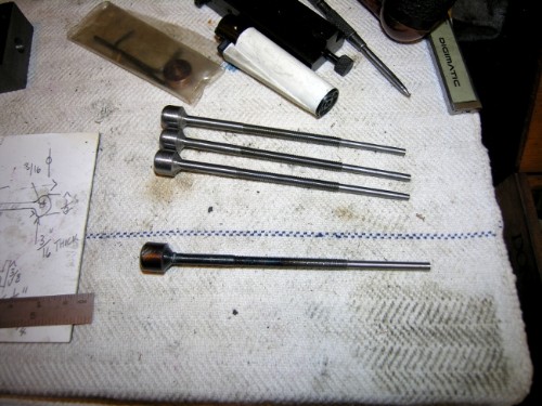
Just for a laugh I warmed it up and straightened it but of course it cracked so back into the lathe, make another and file it to shape, slower but much safer!
Close of play, we have four valve rods! No shame in cocking up but it certainly shakes you out of complacency. I can use to valve rods to ensure the slot in the valves is in line with the glands and guides. This varies slightly between the chests because they all cleaned up slightly differently due to not a lot of metal to play with and natural variations in the surface. No big problems there. Next job is to cut the blanks for the valves to correct size.
Oh, and I shall put right the mistake I made on the guides, the same one I made three years ago whan I made the four FiveAs, I bored the guides 3/16" forgetting I had to thin the rods to clear the nuts. I shall plug the holes and drill them the correct size. Actually in future I'll not bother with the thinning, the rods will not mind being threaded where they go into the guides.
Stanley Challenger Graham
Barlick View
stanley at barnoldswick.freeserve.co.uk |
Stanley
Local Historian & Old Fart
36804 Posts
|
|
Posted - 19/10/2011 : 07:13
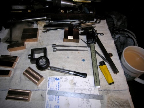
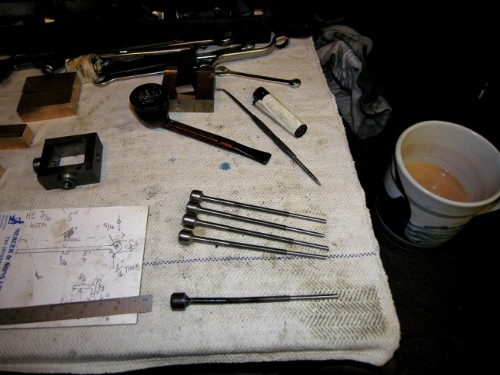
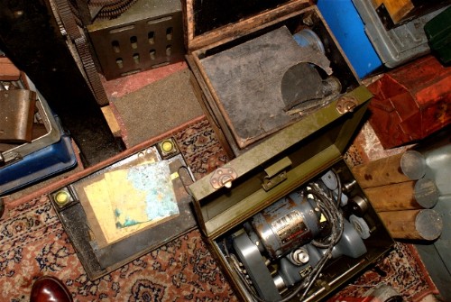
Just struck me. Robert was on about drawings. The small pad is the working sketch I make when I've decided exactly what I want to make, different than Bahrett's obviously. Just a sketch with essential measurements and chucked away when the part is made. Not a fag packet but same thing. If it was good enough for Johnny it'll do me!
Stanley Challenger Graham
Barlick View
stanley at barnoldswick.freeserve.co.uk |
Stanley
Local Historian & Old Fart
36804 Posts
|
|
Posted - 20/10/2011 : 05:51
A day of small steps. All the valve rod guides plugged and bored to correct size. In future I'll leave the boring till I have finished the valve rods, we live and learn!
All valve blocks cut so they will fit in the steam chests. Steam chest face marked 'C' on the block side to make sure I keep them oriented correctly. Lots of checking of port sizes etc. to make sure I know what I'm doing. The blocks need to be milled to the correct size in the right places!
Thinking about making a small tool for screwing studs in, one for 2BA and one for 3BA. It will save a lot of time when I come to erection and finishing. I've considered this before but never got on with it. My mind is wandering round pistons as well, I'm leaning towards bronze because I have plenty of bronze stock.
Amazing how the time flies in the Shed.
Stanley Challenger Graham
Barlick View
stanley at barnoldswick.freeserve.co.uk |
Stanley
Local Historian & Old Fart
36804 Posts
|
|
Posted - 21/10/2011 : 05:54
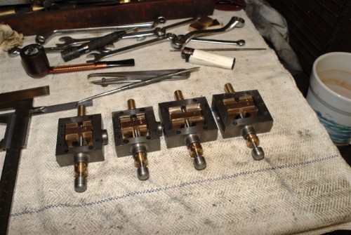
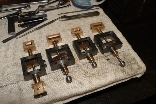
Close of play. All valve blocks square and sized, drilled 4.7mm clearance for the valve rod and the fit confirmed. All valves numbered to match steam chests. Next move is to fit driving blocks and then open the 4.7mm bore to an open topped slot so that the valve is not restrained in any way from seating on the face. Remember that the valve itself is loose and able to move independently of the rod and driving block, all they do is restrain it and keep it in the correct position. Last job will be to cut the steam passage in the lower face and grind the face to a frosted finish so it can seal on the port face.
It's progress and all is going nicely. No shame in taking time over the valves. If they aren't right the engine will never run properly. One thing about lap and lead on slide valves, I don't really understand them and work on the simplest level, making sure that the valve correctly opens the right port at the right time. If it was a full size Corliss engine I would be au fait but slide valves are so bloody complicated! We're not driving a thousand looms! Plenty of books on the 'simple' slide valve if you want to become an expert!
Stanley Challenger Graham
Barlick View
stanley at barnoldswick.freeserve.co.uk |
Stanley
Local Historian & Old Fart
36804 Posts
|
|
Posted - 22/10/2011 : 06:29
Friday is a broken day, real life intervenes! However....
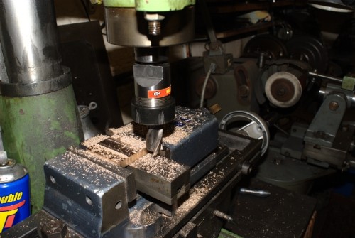
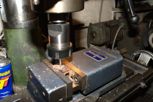
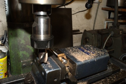
You can't beat the HM and a sharp cutter for milling slots!
Close of play. All the valve blocks milled out for the driving blocks. Next job is to fit the blocks, cut the slot for the rod to sit in and then mill out the steam space under the block. Quietly away, no mistakes!
Stanley Challenger Graham
Barlick View
stanley at barnoldswick.freeserve.co.uk |
Stanley
Local Historian & Old Fart
36804 Posts
|
|
Posted - 23/10/2011 : 06:28
First job yesterday was to mill the blanks for the driver blocks down to the correct fit for the 3/8" slots in the valve bodies. A bit of 'bleeding obvious' here for beginners. Theoretically the same size driver and slot should fit but they won't. 'Fit' is one of the most mysterious elements of fitting, that's where the name comes from. If you search the literature you'll find reams of advice on different grades of 'fit' and they are all valuable but I'm afraid I can't advise you about the theory, I don't know enough about it. My version is that fit is the balance between what works with the least play and what is too sloppy. In this case you have to remember that the valve needs to float on the seat independently of the driver. So make the driver to be a good fit in the slot but give it enough clearance to ensure that it is not restraining the block. It's a matter of individual feel. That's my version of 'fitting'.
You don't need to worry here but this can become complicated when other elements come into play. Even the masters could get caught out. Newton told me about fitting a balanced governor valve to an engine which Johnny had made and try as they might they couldn't get it to work accurately. The fault was that Johnny had fitted a bronze valve in a CI body and when the valve reached working temperature it expanded more than the CI body and the correct fit was lost. In the case of the driver expansion could cause the driver to bind in the slot so you have to remember this when fitting and allow a bit more play. It's a very small discrepancy but if you make the fit too tight you could get into trouble! End of lecture, just make the drivers a 'nice fit'.
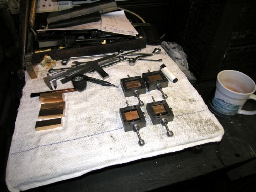
Close of play. The drivers are squared, cut to size, bored and threaded to suit the rods and fitted. We're ready for cutting the slot to relieve any restraint from the rod on the valve. You may wonder why I didn't cut the slot for the rod first. The reason is that due to slight differences in the line of the bosses on the steam chest due to macining being governed by surface flaws in castings that were only just big enough I preferred to fit the valves before marking up for the slot which I want to be a close enough fit to guide the valve block but not to sloppy and allow it to wander. Restraint again wthout binding. You can't take too much trouble over the valves, they are the heart of the engine and if badly fitted the best made engine in the world won't be satisfactory. Onward and upward!
Stanley Challenger Graham
Barlick View
stanley at barnoldswick.freeserve.co.uk |
Stanley
Local Historian & Old Fart
36804 Posts
|
|
Posted - 24/10/2011 : 07:12
We started the day by fitting the gland nutss and guides and adjusting the length of the valve rods.
First job was to mill out the slots for the valve rod. 1/4" cutter in the HM, no dramas! Just take the clearance hole out.
All the slots cut and the drivers fitted to the valves, always a bit of burring to get rid of. See what I mean about the Newton method of valve driving? A lot of work but a very good way of achieving the object and of course they can be adjusted without dismantling the valve.
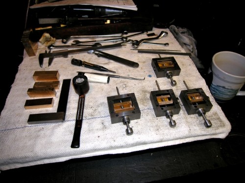
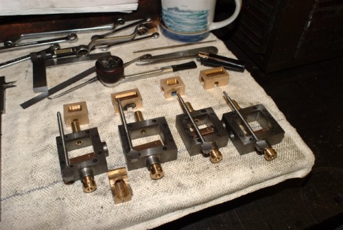
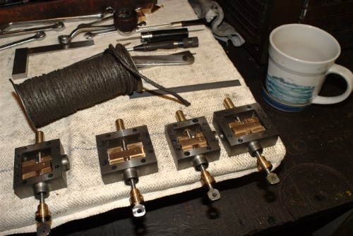
Cutting out the steam passage under the valve. Tiddly work after some careful measuring. Nice to be reaching a conclusion but I hate the fact that if you make a mistake at this stage so much work is wasted. Total concentration! By the way, passage is about 1/8" deep.
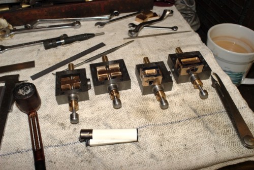
Close of play. All the valves have steam passages like the two on the right. Newtons old slide valve cover is on the bench ready for grinding the bottom faces flat. All that remains now is to cut two flats on the end of the valve rods and drill for an 1/8" hardened pin which will engage with a similar hole in the simple jaw at the end of the eccentric rod. (Forget that size, they will be 3/16"!) This is another departure from Mr Bahrett. He has a complicated split bronze bearing and the jaw on the valve rod. I don't think this is necessary. This isn't a bearing it's just a connection and there is hardly any movement on it when the engine is running so I prefer to keep it simple. Just an aside, when I ran Bancroft engine there were four drip feed lubricators on the links between the tail rod and the bell crank which drove the air pump. Hardly any movement on the links and oil thrown all over the place. I took them off and simply put a drop of cylinder oil in the hole at start-up and dinnertime. Never any problem. On the whole the old engine makers tended to go overboard with oilers and bearings and I always remember what Johnny said to Newton when they were looking at a big loco. Johnny pointed at the small oil reservoir with a cork in the filler hole on the crank pin on the main driver. He said to Newt, "Isn't it funny how that bearing survives with muck and grit flying up at it all the time it's running and on a mill engine crank pin carrying the same power we have complicated banjo oilers dripping oil in all day". He had a point, mind you, I would never have taken that particular oiler off! I used to set the drip feed at one frop every ten revs approximately and wouldn't have liked to go below that.
So, How to mill the flats on the valve rods without running into the danger of another smash? I've been thinking about it.....
Stanley Challenger Graham
Barlick View
stanley at barnoldswick.freeserve.co.uk |
Stanley
Local Historian & Old Fart
36804 Posts
|
|
Posted - 25/10/2011 : 06:47
Kirk, resend the email you sent on Sunday please, I deleted it accidentally.
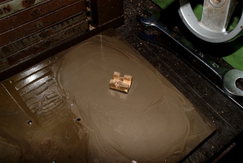
Out with the old slide valve lid and a bit of gentle grinding of the steam valve faces. Slow but accurate and a nice frosted finish that matches the port faces and will bed in well.
All the valves ground to a nice finish. Now for what could be a dodgy bit of milling, putting flats on the ends of the valve rods. Notice the spare crankshaft brass that I made the mistake with. It is going to become a sacrificial milling fixture!
I split the bearing one one side with a saw cut and used to to grip the end of the rod firmly and then started milling. If you look carefully one side has been cut and I've turned the rod over to mill the other side. I wasn't sure how effective this would be but it worked out OK. All the rods flatted with no holding marks on them.
Close of play. All that remains is to drill the valve rod ends for the connecting pins. Forget what I said about 1/8", they will be 3/16" bore. Then a bit of packing in the gland because it's easy to do on the bench. Then fit the steam chests back on the block properly studded and ready for the eccentric rods but they won't be made until the crankshaft is made and accurate measurements can be made for length.
Stanley Challenger Graham
Barlick View
stanley at barnoldswick.freeserve.co.uk |
Stanley
Local Historian & Old Fart
36804 Posts
|
|
Posted - 26/10/2011 : 06:35
Started the day with a funny. I've always said that it took me 40 years to understand sharp edges on cutting tools but have always known that my freehand drill sharpening skills were deficient. A long time ago I bought a Picador drill sharpening jig and never took it out of the box! Don't ask me why....
I got it out yesterday and cracked how to use it and I have to say I should have done it twenty years ago! Sharpened my 3'16" drill before drilling the valve rods and it cut with a continuous curl of swarf from each land, identical to each other. I promise I'll use the jig in future! Mind you, I haven't cracked the backing off and still do that by hand.
Another fuuny.There are many advantages in having a small workshop, everything is to hand. However it means that the box that you need to get into is always the bottom one in the pile so you have to get them all out. I needed to get into my packing sotore box for the next procedure on the valves and here is part of the result. I opened the other box to show you the Dumore grinder that I converted to fit the Harrison lathe. It's American and 110v so I have to run it off a transformer but when you need it it's a brillian tool. This is why things like mylathe centres are so perfect! Enough, what I was after was the graphite and grease packed asbestos string. That's right, asbestos. No danger at all in this form but I bet it's illegal now! Still the best packing....
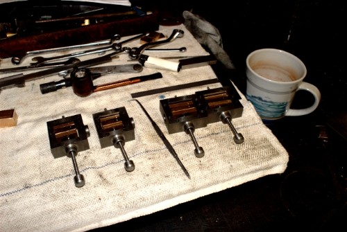
Final stage on the valves. About four inches of string cut off and separated into five strands, one strand for each gland. Pack them and screw them up. Ready for running. The steam chests can go back on the block now.
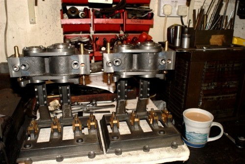
Looking tidy! Decided against fitting more studs. I realised that this was a good opportunity to address the front supports. I've decided how I'm going to fit them so that if necessary they can be removed without dismantling the engine.
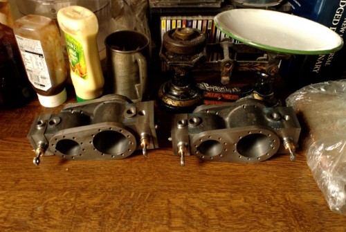
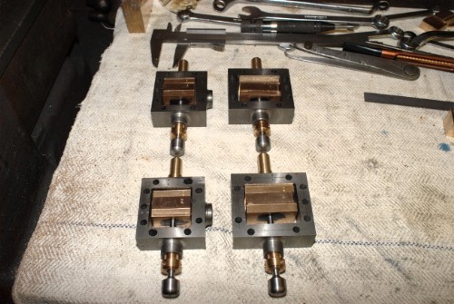
The blocks came off and became ornaments in the kitchen. They begin to look quite impressive. By the way I decided that the lids are going to be bolted down with set screws instead of studs. I hate studding and set screws have exactly the same hold. (I'm old, time is short and set screws are quicker!)
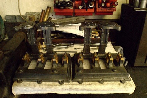
The beds are ready for shaving. I need to do some accurate measuring of angles so I can face the lugs on the bottom lids and the pads on the bed to get a good fit. I shan't bother under the bed, a wedge washer will take care of that misalignment and never be seen.
It will be nice to make some shiny bits!
Stanley Challenger Graham
Barlick View
stanley at barnoldswick.freeserve.co.uk |
Stanley
Local Historian & Old Fart
36804 Posts
|
|
Posted - 26/10/2011 : 06:54
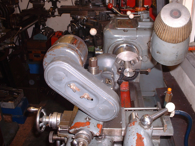
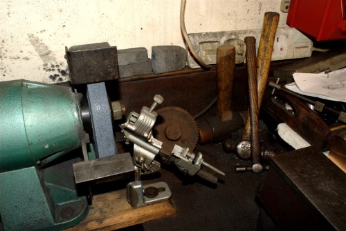
Here's the Dumore grinder on the Harrison. The clamp on the workpiece is the holder for the diamond dresser that comes with the grinder. You can dress the wheel lightly to ensure a perfect match with the surface you are going to grind. I got the grinder in a workshop deal and though old it has seen very little use. I forget the motor speed, I have an idea it is about 10,000rpm, it doesn't half whine when it's running and though totally enclosed it runs cool. A good tool and it has internal grinding spindles as well.
So why not grind the bores on my engine blocks? It would improve them slightly but thinking back to the old fitters, they never ground the bores. They knew that a good bored finish soon mated with the CI rings and if you look at the bore of an old engine it's perfect, polished and has a skin on it that only comes with running. This applied even in marine engines where the bores were never lubricated. The lubrication was the steam. Newton told me that the standard rings were Rowan Rings and he said it was amazing how long they would run without maintenance. (No lubrication because the last thing you wanted was oil in the feed water enclosed system because it would burn the boiler tubes out.)
Stanley Challenger Graham
Barlick View
stanley at barnoldswick.freeserve.co.uk |