| Author |
 Topic Topic  |
|
Stanley
Local Historian & Old Fart


36804 Posts

|
|
 Posted -
25/11/2004
:
14:20 Posted -
25/11/2004
:
14:20
|
I've always been fascinated by the things people do in their spare time when they can do exactly what they want to do. Men and sheds are a particularly fertile field. Women tend to do their thing in the comfort of the house.
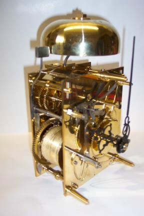
I was delighted to see Andy's picture of the clock movement he has made.
It struck me that we could perhaps start a new topic devoted to spare time skill. So Andy starts it off and my contribution is this:
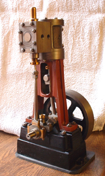
It's a small steam engine made from scratch and is based on the Stuart 5A but a longer stroke. One of these will drive a 14 foot boat with steam at 250psi. By the way, we don't like to call them models, it's exactly the same construction and materials as a full size engine, just smaller. So come on out there, let's hear about what you make in your spare time. I reckon we could be in for some surprises!
Stanley Challenger Graham

Barlick View
stanley at barnoldswick.freeserve.co.uk
|
|
| Replies |
| Author |
|
|
Bodger
|
Posted - 12/07/2008 : 15:09
Stanley, the opposite handle direction is a new one on me, i have used lathes in various countries, and of various makes, but they all operated the same way, anticlockwise to move the saddle to chuck, cross & compound slide, clockwise to the workpiece,
"You can only make as well as you can measure"
Joseph Whitworth
 |
Stanley
Local Historian & Old Fart
36804 Posts
|
|
Posted - 12/07/2008 : 17:24
It varies on the opld ones Bodge, depends on whether the gear acts on the lead screw above or below the c/line and whether there is an idler gear in between.
Stanley Challenger Graham
Barlick View
stanley at barnoldswick.freeserve.co.uk |
Stanley
Local Historian & Old Fart
36804 Posts
|
|
Posted - 13/07/2008 : 09:03
I decided to repair an old ball-turning attachment I have but then looked on the web..... Have a look at this and run the videos. I'm going to make this!
http://bedair.org/Ball/ball.html
Stanley Challenger Graham
Barlick View
stanley at barnoldswick.freeserve.co.uk |
Stanley
Local Historian & Old Fart
36804 Posts
|
|
Posted - 14/07/2008 : 08:55
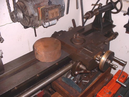
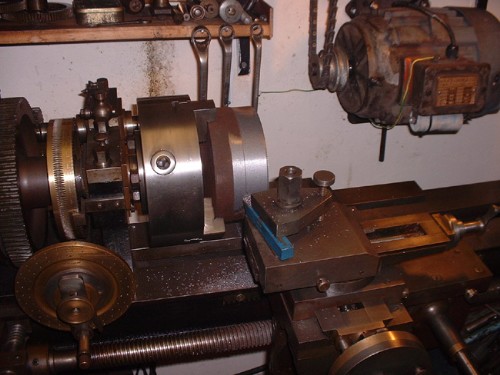
I've done my thinking and I'm going to follow the basic design of the Bedair attachment but I think I can simplify it by fitting it directly on the cross slide of the 1950 lathe. I've got some more measuring to do but I think it will be OK because the 1950 lathe is such a big lathe. The limiting factor is the centre height above the cross-slide and the size of balls I will want to make should fit into this. First thing of course was to get into the treasure box and find a lump of cast..... I have one and once more the policy of never walking past a useful lump is proved to be right. I think we have enough meat here!
By the way, Johnny made a good job of his circular channel for the holding down bolts and I'm pretty certain that the attachment will rotate smoothly with just a nip on the bolts. I shall make sure that the base has an accurate annular ring to fit into the groove.
Stanley Challenger Graham
Barlick View
stanley at barnoldswick.freeserve.co.uk |
Stanley
Local Historian & Old Fart
36804 Posts
|
|
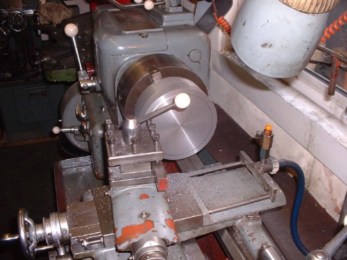
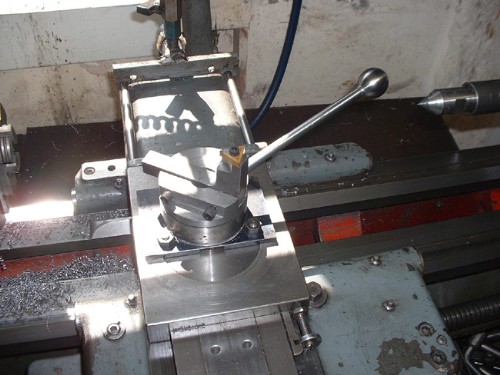
Posted - 14/07/2008 : 18:11
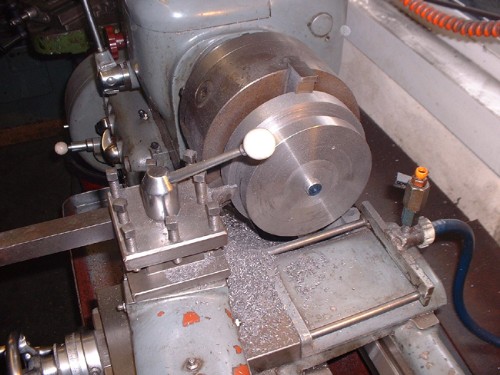
Big chuck on and away we go:
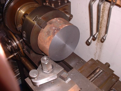
No cross feed so facing is by hand, back to the old days!
No probs with traverse. The lathe was running in back gear at about 60rpm and no problems at all except that it's hard work on the motor. Runs a bit warm but it will stand it. The casting has too much meat and to make life easier I might reduce it on the Harrison because I have power cross feed. I'm not a masochist!
Stanley Challenger Graham
Barlick View
stanley at barnoldswick.freeserve.co.uk |
Stanley
Local Historian & Old Fart
36804 Posts
|
|
Posted - 15/07/2008 : 18:13
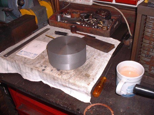
It's been a leisurely and interesting day. We now have a tidy block of cast iron that is about an inch too thick and over an inch to big in diameter. Better than the other way round. I finished cleaning it up in the 1950 lathe and was a bit perturbed when the Horace Green motor warmed up even faster than yesterday. Very worrying. However I pushed on, finished squaring the workpiece up and after I had taken it out I fitted the Taylor chuck, put the same lump in that I used for measuring the revs in direct drive, hung the clock up over the lathe and did some counting in back gear. The full range of speeds is as follows, bottom four in back gear (low range on the Harrison) and top four in direct drive. All RPM of course and the figures in brackets are the equivalent on the Harrison. 16 (34), 40 (48), 64 (75), 108 (117), 160 (216), 328 (306), 556 (479), 1128 (750). So it looks as though the lineshaft speed is about right. The interesting bit came when I took the 1950 lathe out of back gear and locked the clutch for direct drive. The mandrel was solid, I couldn't turn it by hand. A bit of a study and half a pipe of tobacco and I slacked the headstock bearing nuts behind the chuck, instant success. No wonder the motor was warming up, I'd been running with the headstock bearing far too tight. Funny thing is that one of the things I had been checking constantly, because it's the hardest cutting I've ever done on the lathe, was the temperature of the bearings on the mandrel and the lineshaft. Before starting the heavy cuts I'd checked the tightness of the nuts on the bearing caps and must have done it with the spindle running and assumed because there was no change in motor spoeed or warming of the bearing that I had it right. Just goes to show how wrong you can be. In my defence I have always adjusted plain bearings by running them and checking temoerature, on a big engine bearing it's the only way you can do it because they are too big to try by hand. What I did was exactly that but I forgot that this bearing is much more closely fitted than any engine bearing, it's more accurately made and most important, it's a tapered bearing and the adjustment for wear is to force the shaft into the bearing with a jack screw on the end of the mandrel wich puts pressure on the thrust bearing just outside the headstock. Bit of a learning curve, no damage done because there was no heat. The surprising thing isthat the Horace Green just carried on as though all was well. I don't know enough about electric motors to know about torque figures but I suspect that this motor has a very high one! The overload in the starter is set at the running amperage of the motor and is very sensitive, it never tripped out. Quite impressive. Another thing that I jave inadvertently proved is that the belt tensions, though low, are adequate. There was no detectable belt slip even under these adverse conditions. All par for the course, learning about Johnny's lathe and its capabilities. So, despite my mistake, an interesting and reassuring day! (Always look on the bright side of life, dee dum, dee dum....)
By the way, I considered cutting the extra inch off the end of the blank by cutting on the horizontal miller as far as I could with a slitting saw and finishing with the hacksaw but I decided that life is too short. I can do it with far less effort on the Harrison. Plenty of CI muck tomorrow.
Stanley Challenger Graham
Barlick View
stanley at barnoldswick.freeserve.co.uk |
Stanley
Local Historian & Old Fart
36804 Posts
|
|
Posted - 16/07/2008 : 18:34
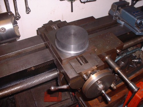
First thing to say is that this is one of the nicest pieces of CI I have ever had the pleasure to meet. Whever cast this had access to good materials and knew his job.
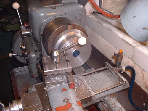
First job was to reduce this end to 5 1/2" diameter and 2 1/4" thick. Then turn the spigot to fit the saddle on the 1950 lathe and then start digging into the side to give space for the nuts on the holding down bolts. The annular groove is 1/2" wide and has to be 1 1/2" deep. Funny, but as I type this I have just realised that the easiest way to do it is to mill the seatings out! I shall clean the groove up and mill them out tomorrow. Nowt lost as the groove as it stands gives more swing on the spanner. I know that the way I am doing this is not efficient, wastes material and takes too much time. But there you are, I have no gaffer breathing down me neck, the CI cost nothing and I'm as happy as a pig in shit making CI muck! Johnny would smile as well because the big parting tool I am using was his favourite. Newton gave it me because he thought it was too big. Another nice day......
Stanley Challenger Graham
Barlick View
stanley at barnoldswick.freeserve.co.uk |
Bodger
|
Posted - 16/07/2008 : 20:15
Stanley, not sure if i gave you this link before ?, the guy Newbould designed and made an impossible device for setting angles on machine tools without sine bars, angles can be set in a fraction of the time usually required, it is a long forum, 300+ posts, but if you get bored go to page 18, he describes producing shafts to 5 millionths of an inch, i thought iwas good working to a tenth of a thou !http://www.practicalmachinist.com/vb/showthread.php?t=159279
"You can only make as well as you can measure"
Joseph Whitworth
|
Bodger
|
Posted - 16/07/2008 : 20:28
Stanley the last ref. should read page 16 - 18
"You can only make as well as you can measure"
Joseph Whitworth
|
Stanley
Local Historian & Old Fart
36804 Posts
|
|
Posted - 17/07/2008 : 06:48
Bodge, I wouldn't recognise a millionth of an inch if it jumped up and punched me on the nose!
Stanley Challenger Graham
Barlick View
stanley at barnoldswick.freeserve.co.uk |
Stanley
Local Historian & Old Fart
36804 Posts
|
|
Posted - 17/07/2008 : 17:05
It's been a funny old day......
I've got the base finished and fitted on the cross slide, nice and tight and it was obvious that with a bit of grease under the base it would rotate nicely with no play. Ready to mill the gaps for the nuts and mill the slot out for the cutting head.
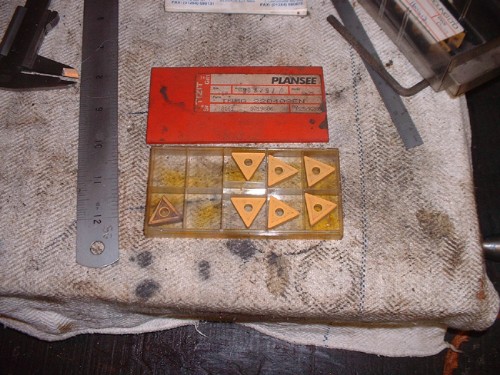
In me treasures I have some sintered carbide cutting tips. I haven't a cutter for these particular ones, I must have won them somewhere. 6 cutting edges on each by rotating and then turning over. I'll never wear one of these out so I decided to make the toolholder while the slitting saw was still in the H mill. So some quiet blueing up, marking out etc. Then something struck me...... I went and checked and sure enough I had a bit of a problem. In order for the ball turning attachment to work the centre of the rotating tool holder has to be in line with the centre line of the chuck. The centre of the cross slide on Johnny's lathe stops an inch short. Bugger! I think I'd been working on the assumprion that the centre passed the lathe centre line because it does on the Harrison. All right, I should have done more measuring and drawings and thinking..... I'm a bit like Newton, sketch it out on a fag packet, get the essential measurements done and then get going. I shall have to have a bit of a rethink....... They call it engineering!
Stanley Challenger Graham
Barlick View
stanley at barnoldswick.freeserve.co.uk |
Stanley
Local Historian & Old Fart
36804 Posts
|
|
Posted - 23/07/2008 : 05:21
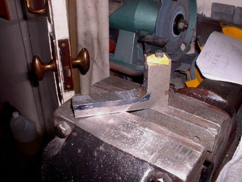
Well, I've licked my wounds for a day or two, had a complete rethink and ditched what I had done before except for the toolholder. I did a bit on that yesterday and here it is half finished. Everything else gets made to fit this and the finished tool will mount directly into the toolholder on the compound slide. We are moving forward again.
Stanley Challenger Graham
Barlick View
stanley at barnoldswick.freeserve.co.uk |
Stanley
Local Historian & Old Fart
36804 Posts
|
|
Posted - 23/07/2008 : 17:15
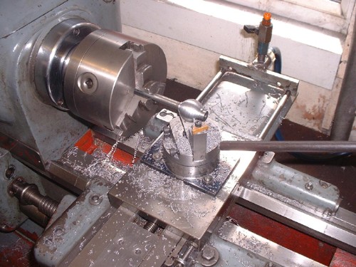
The tool holder is finished, the tool block and its mounting screw are made and the tool holder fitted. This needs a couple of set screws fitting to lock the tool holder and a hole drilling in the side for the operating handle. Then I can measure up and think about the foundation plate and the attachment to the tool holder. This will work.......
Stanley Challenger Graham
Barlick View
stanley at barnoldswick.freeserve.co.uk |
Stanley
Local Historian & Old Fart
36804 Posts
|
|
Posted - 26/07/2008 : 17:37
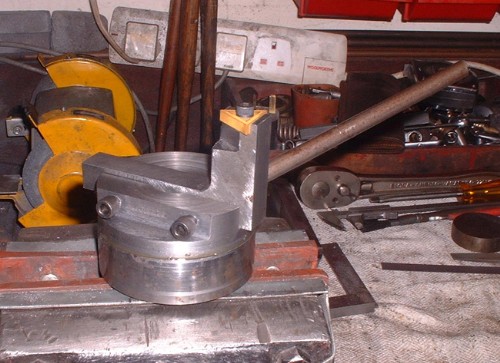
Yes, I know, I've been quiet for a day or two but progress has been made. The attachment is almost finished, only the handle to clean up and of course, a ball fitted to it! I ground the two faces of the holder and the block together, cleaned them up, a spot of grease and reassemble. It works beautifully, slight resistance but smooth and no shake. I went through several options for the actual mounting on the cross slide and then had a thought. I looked at the Harrison and worked out that the mounting was dead simple, just a piece of 3" by 4 1/2" x 1/4 plate and would you believe there was a piece in the treasure chest exactly the right size. This is cleaned up, mounting holes for the cross slide drilled and in the middle of fitting. It will then get fitted to the base of the attachment by two countersunk screws and have a hole cut in the middle to give access to the adjustment nut for the turntable. Very close now.......
Stanley Challenger Graham
Barlick View
stanley at barnoldswick.freeserve.co.uk |
Stanley
Local Historian & Old Fart
36804 Posts
|
|
Posted - 27/07/2008 : 16:23
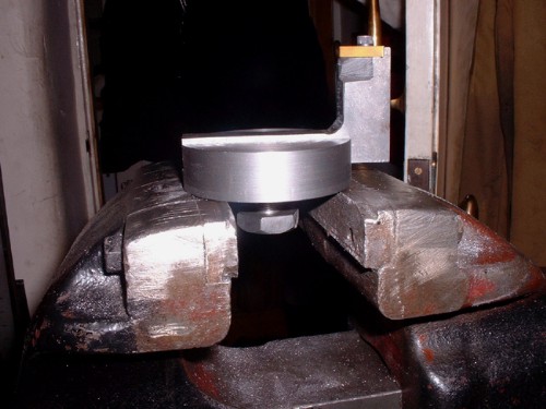
Here we are, finished apart from an operating handle with a ball on the end of it. I mounted the attachment this morning and thge only adjustment needed was a .0030 shim in between the mounting block and the square plate. I soon found that there was a problem in the shape of the cutting block head and had to do a bit of pruning but soon got it right and started cutting.
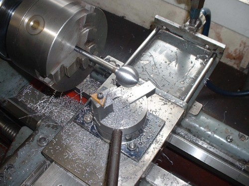
Here we are after about 15 minutes very careful cutting. Not quite round, but that's all to do with my not getting the setup quite right. The next time I make one I shall do a lot more careful measuring! I didn't chase the finish with the tool because a carbide tip is never going to be perfect. I resorted to diminishing grades of emery.
Here we are, a perfectly acceptable finial on the handle and very easy on the hand. The fit of the block on the mounting is pwerfect and I soon found that anything beyond a nip on the toolhoder screws distorted the face and tightened it up. The fit is good and no chatter at all from loose tooling.
All told, very pleased with a first attempt. The design of the attachment is good and doesn't need any changes. If I did make a change it would be to make another toolholder to take a 1/4" square HSS cutter and see how that performed.
Stanley Challenger Graham
Barlick View
stanley at barnoldswick.freeserve.co.uk |