| Author |
 Topic Topic  |
|
Stanley
Local Historian & Old Fart


36804 Posts

|
|
 Posted -
29/07/2011
:
06:27 Posted -
29/07/2011
:
06:27
|
New start as old topic was getting too big. Here's the LINK for the original topic.
Sheds are centres of honest endeavour and sanity, rare things these days. Please join in and tell us what you are doing in your shed. All are welcome!
[By the way, if I occasionally seem to be stating the bleeding obvious, it's because I'm aware of the fact that not everybody has the same experience so please forgive me.]
Stanley Challenger Graham

Barlick View
stanley at barnoldswick.freeserve.co.uk
|
|
| Replies |
| Author |
|
|
Tizer
|
Posted - 13/11/2011 : 10:41
When we go to the far end of Cornwall for our holidays I like to take a trip to Pendeen, home of Geevor and Levant tin mines/engines. We look in at the shop run by Mr & Mrs Hobbs in the centre of the village (park in the village car park and it's alongside) where they sell mineral specimens, fossils, and also jewellery made by Mr Hobbs in the workshop. They've been doing it for 30 years or more. Last time we went Mrs Hobbs said that the jewellery on display was the last there would be from Mr Hobbs, and we thought, oh dear, has the poor man had a stroke or perhaps even died. When we enquired why, Mrs Hobbs replied "He's discovered model steam engines".
 |
Stanley
Local Historian & Old Fart
36804 Posts
|
|
Posted - 14/11/2011 : 07:05
Tiz, what a sensible Bloke! I'll bet he's been nursing the urge for years but had to make a living. He will now go out in a blaze of glory!
Askers, errors on full size engines would be a long list. One of the best accounts I ever found was 'Engineering Reminicencies by Charles T Poerter of governor fame. He is particularly scathing about Whitworth in his later years! As for engines I have run, a few examples.
Bancroft. Roberts got the upset wrong on the LP piston rod. Newton told me that the old fitters used to bend the piston rods so that when the weight of the piston was on it, the rod was straight. Without the upset the rod sagged. Bancroft had problems with the LP amd Roberts couldn't or wouldn't alter it. After all, the faster it wore out the sooner they got another order! Henry Brown's want in and turned the piston and rod through 180 degrees and cured the problem. There was the small matter of getting thelevel of the engine beds too high in relation to the water level in the dam and all its life the engine suffered from too much lift from the dam reducing the vacuum you could get. This was made worse by the fact that Roberts had their own ideas about air pumps and incorporated side chambers to give an air cushion in the body of the pump. Never worked, the chambers filled with water and resulted in too much water sloshing round in the body that was never cleared.Johnny wanted to put an Edward's pump in, he reckoned it would give 30" vacuum but the management never got round to it. Worst fault was that when they made the LP pedestal they forgot to raise the boring bar for an additional cut after the final boring cut so as to give clearance in the bottom of the cap. If you go to Bancroft you'll find that the cap nuts are loose, if you tighten them hand tight you'll be stopped in ten minutes with a hot brass. I wanted to fit packing blocks under the cap but never got round to it.
Whitelees had several faults. Worst was that they got the length of the eduction pipe from the condenser to the cylinder 2" too high and to compensate for this they mounted the cylinder two inches higher so there was no clearance in the bottom. Long story but at some time it cracked the entablature beam most likely because of water in the cylinder base. When I rebuilt it I didn't know about this. mounted the cylinder correctly and then found that the air pump bucket hit the delivery plate at the top of the stroke. Cure was to put a two inch Tufnol ring inbetween the coffin bottom and the air pump body. I'll bet nobody has ever noticed it!
Ellenroad had several peculiarities. To be fair, some of them dating from the conversion to double tandem from triple expansion. The LP cylinders were too small for the new HPs and they must have run them at very high pressure. On the tight hand engine the front inlet port chamber is cracked, plated and held on the iside by a screw jack which is still in there! Left hand LP gathers water during light running and after a while you had to run with the front drain open. If you've never heard a slug hitiing the front cover of a 43" cylinder every stroke you don't know what priming is! The pedestal bearings on the 85 ton flywheel aren't big enough. It's the only engine I have ever run with water cooling pipes in the oil pump reservoirs! Never a problem while running without ropes but it must have been exciting whan they were running with 1500hp on each engine!
Biggest planing machine I ever saw was at a tank factory in leeds. When I was taken to see it I asked where it was and was told I was standing on the bed! They used it for planing the turret rings on two tank bodies at once.
Sorry I have caused you so much angst by tempting you back into the Shed! I had my share of working with worn lathes and inadequate tackle and to tell the truth I went overboard when I was building the present Shed up. I got the best of everything and at times wondered whether I was just a collector. Newton kept me straight and always supported me, I think he knew I'd eventually become a half decent fitter! My view is that I have enough handicaps without introducing problems caused by inadequate tackle!
I doubt if you are the world's slowest machinist. I think I might get that prize. Newton was raised in an ethos where speed was essential and I used to watch in awae as he took huge cuts, blue swarf, and then a tiny finishing cut that left a perfect finish with the same tool.
I think one of the advatages about living in the cab of a wagon for so many years is that you have to be clean and tidy. Last job I did last night was to get all my ducks in a row for today, clean the machines down and even vacuum the carpet. I'm very good at having a place for everything and everything in its proper place. As I am the only worker, things always get put back in the same place! Hoever, it didn't happen by accident. I got so fed up of spending hours looking for the right tool or holding down bolt that I did something about it. Some people will see it as overkill but it suits me.
As for stupid mistakes, we all make them and I always tell my readers about mine. That's the way you learn. As for the finished result, you are never satisfied because you know where all the errors are. Like the piston rod out of line. You either go into a decline and start again or you work round it. I always remember the cartoon with the caption " When you're up to your arse in alligators, it's sometimes hard to remember that the primary objective was to drain the swamp!" That's why I try to remember, the primary objective is to make an engine that runs. This foes back to the old fitters and the mistakes I have detailed above, all those engines had a long and useful life and are still running despite the mistakes. In the end that's all that matters!
Right! Yesterday.
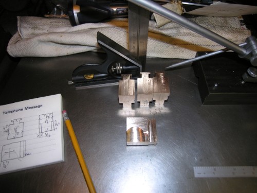
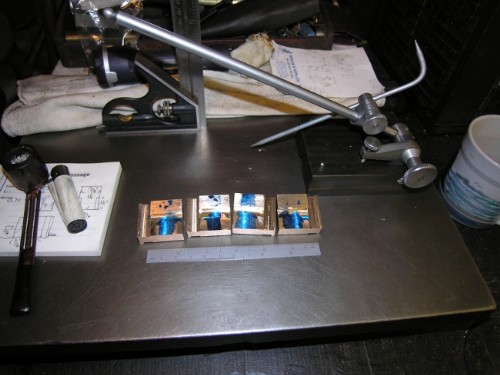
First job was to finish squaring the blanks for the crossheads so that they can be marked accurately.
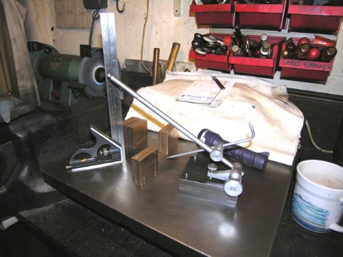
A nice illustration of the advantages of having good tackle. The most accurate and quickest way to mark the blocks is on the surface plate using an accurate square and a scribing block. Dead easy and fast! Incase you're wondering the torch is for spot lighting of the scale to make sure I have the scriber point at the right height. Cataracts are a bugger!
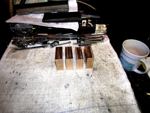
End result, marked accurately and a cross on the part you want end up with just to make sure you don't get mixed up!
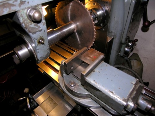
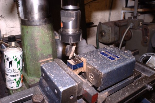
Blleding obvious again. Best way to make sure the vise is set parallel to the slitting saw is to put your best engineer's square in it and make sure it is in line with the saw. If you only have one square, make it a good one! Anything that's in good condition with Moore and Wright and a BS number stamped on it will do nicely.
Close of play. First block mounted and ready for the first cut. A good clan up, tidy stuff away and vacuum the carpet! Those brass milling chips get everywhere. (I had a very sharp one in my underpants in just the right place to cause maximum discomfort! The tribulations we have to suffer for our art!)
Stanley Challenger Graham
Barlick View
stanley at barnoldswick.freeserve.co.uk |
Invernahaille
|
Posted - 14/11/2011 : 22:52
A pawnbrokers sign Stanley?
|
Asquith
New Member

23 Posts

|
|
Posted - 14/11/2011 : 23:22
Stanley
Many thanks for the anecdotes (about the engines, not the private information!).
If only these old steam engines could speak, rather than just groan or knock. The Culverwell horizontal engine at Westonzoyland has recently acquired a knock. We opened up the cylinder yesterday to find that the piston was hitting the cylinder cover at the gland end (I'd call it the back, but I think the correct parlance is front!). Relative to the cylinder, the piston is biased towards the crank, by about 5/16”.
The likely candidate initially seemed to be that the cylinder had moved on the bedplate. Although it was apparently dowelled, the ‘dowels’ were actually bolts in the dowel holes, and they didn’t actually get beyond the cylinder, there being no holes in the bedplate! On the other hand, there were dowel holes elsewhere which made us wonder whether the cylinder had been changed at some point.
The cylinder’s main holding down bolts were quite a close fit, so it couldn’t have moved much, but we figured that with recent running the cylinder had moved just enough to allow the piston the start hitting the end.
Another oddity is that although the piston is positioned too far back in relation to the cylinder, the crosshead is too far forward in relation to its guides. In fact the crosshead and its guides had been suffered impact damage in the distant past, and had been repaired.
We’ll get it sorted, but it’s interesting to study these (and other) anomalies and wonder what occurred during the engine’s days in a brewery.
Slow progress on my model engine today. I decided to machine the slender slide bars, and thought I’d give my ’pre-owned’ Eclipse magnetic base its first airing since I bought it on the off chance a few years ago. It works well - now I’ve got round to making a handle for it.
|
Stanley
Local Historian & Old Fart
36804 Posts
|
|
Posted - 15/11/2011 : 06:37
John, the joys of old engines! If I were you, before I started getting radical with the cylinder I'd have a careful look at the crosshead bearing. You might be surprised what you find!
Started the day nicely with four blanks ready for machining to shape. They look a bit smaller now!

Some careful measuring, sharpen a half inch cutter and away we go. Got one blank reduced and started on the next at close of play. Progress.
However, as I was laid in bed thinking over the day and tomorrow it struck me that there was something wrong! Had a look this morning and unless I am very much mistaken, the dyslexia has struck again! I have machined the wrong side! I shall check up and take a view. Not necessarily a disaster but at the moment I can't get my head round it. Ah well, bum fitter syndrome again!
Stanley Challenger Graham
Barlick View
stanley at barnoldswick.freeserve.co.uk |
Asquith
New Member
23 Posts
|
|
Posted - 15/11/2011 : 21:35
Stanley,
I make too many mistakes like that.
Regarding the Culverwell engine, the crosshead bearing (or rather the little end bearing) did hold another of the engine’s little secrets.
It’s the common old-fashioned type, which has the half bearings clamped in place by a U-shaped strap, all held tight by a gib and cotter.
I removed the tapered cotter, and turned the flywheel a bit to free off the strap. To my surprise there was a clunk, and the strap appeared to have sprung forward.
In fact it had sprung forward. Between the end of the connecting rod and the back of the half bearing there was a stack of shims and a phosphor bronze strip bent to a V shape to serve as a spring! Also, the back of the gib had a piece of strip riveted to it to make it wider. I can only surmise that once upon a time the bearing had worn oval, so they machined the half joints back and rebored, and then had to make up the space with the various shims and packers. But why the spring, I don’t know.
|
Stanley
Local Historian & Old Fart
36804 Posts
|
|
Posted - 16/11/2011 : 06:57
Re crosshead.... God knows but he is keeping quiet! It sounds to me as though you need to start from square one. The original fitters marks may still be on the crosshead and the slide. There should be three marks on the slide, TDC, BTC and centre. If not, make your own. Find the flywheel centre and the two end points by barring round, The centre point on Fwheel should coincide with centre point of piston in the bore. If it doesn't, first look to see whether discrepancy can be cured at crosshead bearing by centre of bore or attachment of piston rod to crosshead. If not look to position of the cylinder on the bed. That was where I went wrong when rebuilding the Whitelees, I wrongly assumed that the original fitters had positioned the cylinder correctly in relation to flywheel centres but of course they hadn't, they had cheated! So don't assume the original fitters were right! (All right, you knew all this but someone may be reading this who needs the full destructions!)
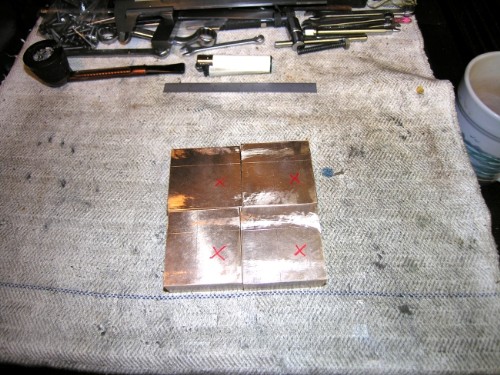
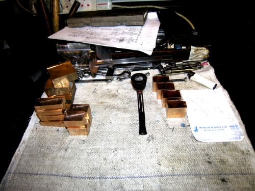
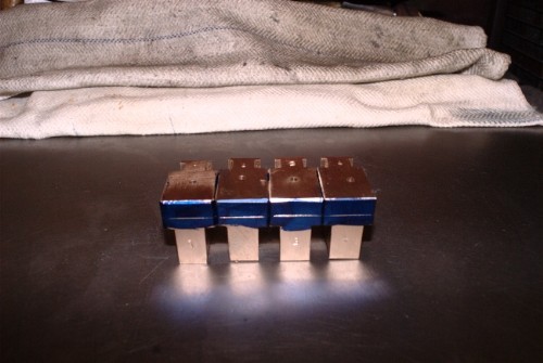
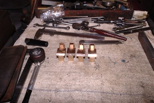
I was right. I had machined the 'wrong' face. I started by machining all the blocks as I originally intended. The two on the right are the 'wrong' ones and on the left as I intended. At this point I had an idea it wasn't the disaster it looked so I carried on with the next cuts on the mistakes.
I think you can see where I am going here, this is the first cut that forms the 'T' section that engages in the crosshead guides. Did one block and offered it up to the guides.
Straight off the mill and the crosshead is a good tight fit in the guide on the first cylinder. No problems there, a bit of careful adjustment and it will be fine.
The interesting thing is that as soon as I had the block in the guide the mists cleared and my brain grasped the orientation and shape. Far from being a mistake, I shall have to reduce the two 'correct' blocks to the same thickness as the 'mistakes' as this is where the jaw of the con rod will fit. It turned out that my brain had been working on the right lines even though I couldn't interpret the instructions! Providence and in this case instict looking after bum fitters!
I shall form the 'T' section on the rest of the blocks and then take a view as to what needs chewing off to get my piston and con rod attachment. It strikes me how much metal I have cut off the original blanks. Completely non-profitable but as I said, who cares! I have enough bronze to last me out! I think I have decided on the piston rod attachment. I had the option of accepted practice, wedging into the crosshead with a cotter or simply threading the rod and screwing it in. I am favouring the latter, it's a table model, we aren't driving a ship! It will look clean and tidy as well.
So, a far happier bunny this morning. Onward and upward!
Stanley Challenger Graham
Barlick View
stanley at barnoldswick.freeserve.co.uk |
Stanley
Local Historian & Old Fart
36804 Posts
|
|
Posted - 17/11/2011 : 06:52
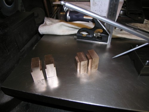
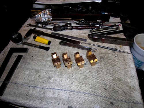
An hour of careful milling and I have all the blocks close to a fit, final adjustments later. Don't worry about the match at the base of the third block along, it's a looser fit and the match is just holding it in place.
Not a mistake. All the blocks thinned down to 1/2" for the con rod jaws.
Close of play. One block milled out in an arc to allow the jaw on the con rod to swing. I shall do the rest this morning, then drill 1/4" for the con rod pin then a bit of careful milling to an arc on the bottom of the block to allow the jaw to swing in the crosshead. Then we come to fitting the crossheads so they slide nicely then marking the piston rod locations and fitting them. Funny that I was talking about fitting crossheads to stroke yesterday to John. I shall have to do the same thing to get the correct piston rod length. If you remember I made the pistons sloppy so I shall pack them before deciding on the drilling position for the rod. The packings will set the centre line not the fit of the piston in the bore. Mind you, I could always make dummy pistons that fit perfectly and use them to find the correct location......
Stanley Challenger Graham
Barlick View
stanley at barnoldswick.freeserve.co.uk |
Stanley
Local Historian & Old Fart
36804 Posts
|
|
Posted - 18/11/2011 : 06:37
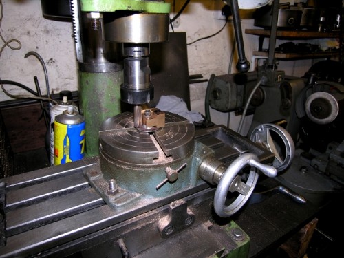
Had a rethink about the web at the base of the crosshead for the con rod jaw and decided it would be better and tidier if it was milled straight across. Then I turned my mind towards the position of the con rod pin and the shaping of the bottom of the web to accept the swing of the jaw on the pin. No problems about position of the1/4" hole for the pin, in line with the piston rod location, and obvious that the answer to the shaping for the swing was milling on the rotary table. However....
Many years ago my mate Paul at Rochdale Welding had his van stolen and lost all his tools. I had more spares than you could poke a stick at so I had a quick trawl and found him a bunch of good basic tools to get him going again. He never forgot this and occasionally he'd turn up with something for me. One day he brought in a 6" rotary table in good nick and asked me what it was and whether it was any good to me. I grabbed it of course! Now, the funny thing about it was that it had no central threaded hole for a locating set screw and over the years, whan faced with rotary milling on items with a hole smaller than the 3/8" hole in my other table I have had to make fancy studs to get over the problem. Yesterday I bit the bullet, stripped Paul's rotary table down and drilled and threaded the centre for a 1/4"Whit socket head screw. Just right for milling the radius on the crossheads. God knows why I have never done it before, took far less time than making a special stud and far better.
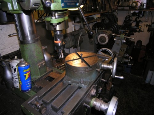
So, half an hour later, all set up and ready to go. First thing this morning will be to mark and drill the crosshead pin holes, make a collar to go under the web to support it dead level and then mill the radius on the web. However, Friday is a bitty day, household tasks press in on me. Might break a rule and go into the shed this afternoon. There is also the question of some articles for the BET. I need to do some writing over the weekend. Unfortunately the Shed has to take second place! Worse than being a worker......
Stanley Challenger Graham
Barlick View
stanley at barnoldswick.freeserve.co.uk |
Stanley
Local Historian & Old Fart
36804 Posts
|
|
Posted - 19/11/2011 : 05:08
Busy day Friday so shed time was limited. However, I marked the con rod pin holes up and made the small collar for the blocks to sit on when milling the curve.
Stanley Challenger Graham
Barlick View
stanley at barnoldswick.freeserve.co.uk |
Stanley
Local Historian & Old Fart
36804 Posts
|
|
Posted - 20/11/2011 : 06:00
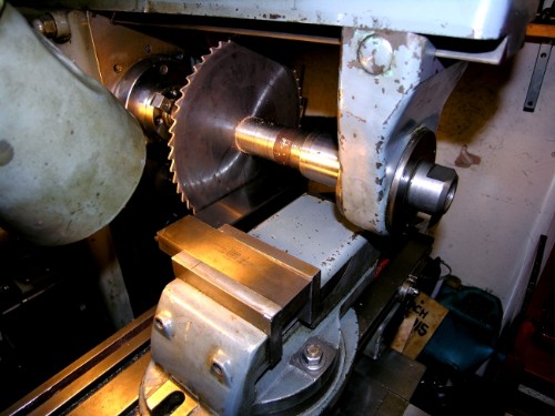
All set up so a side-cutting milling cutter in the VM and a bit of quiet chewing away at the crossheads.
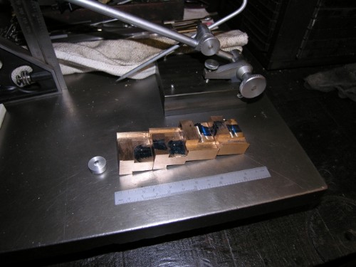
Soon had them all cut away to accept the jaw of the con rod. I'll almost certainly have to adjust the jaws to give perfect clearance but won't have to do any more modification to the curve on the crosshead. I shan't know what is needed until I have the cshaft made and the con rod roughly fitted and by that time the crossheads will be a permanent fixture, Don't want to be pulling them down again! Now we have all the crossheads ready we can pack the pistons to make sure they are on centre line and mark the crossheads for drilling for the piston rods.
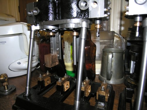
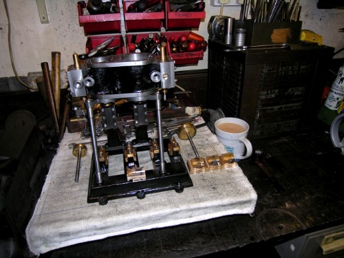
HP piston packed to a tight fit in the bore. The Jubilee clip keeps it compressed while driving it in with a wooden dolly. Get the packing as tight as you can without being solid at this point, it will soon loosen up when the engine is turned over and the better it is fitted the tighter the seal. These packings are surprisingly durable and I doubt if anyone will ever have to replace them.
Close of play. First HP cosshead is marked for piston rod housing. I shall start today with the LP. I didn't pack the gland, no need, the piston packing has centred the rod as near perfect as makes no difference. I shall use these packed pistons for marking the No. 2 engine crossheads as well. The bores are identical and so the pistons and rods are interchangeable at this point. They will only become paired when adjusted to length. As a matter of fact I expect all the rods to be near enough the same length as I have been as careful as possible in my measurements throughout.
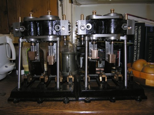
Once all the crossheads are marked, packings out of the two pistons and then find the centre line of the stroke on the crosshead guides. This gives me my datum for deciding the finished length of the piston rods.
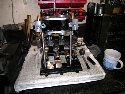
I don't know whether you have noticed but once the crossheads are ready for the piston rods they can be given their finishing polish and fitted permanently. Then the top lids can be finally installed and sealed and the top end of the engines are finished. We will be ready for the bottom end, the crankshafts and motion. All the accounts I have ever found of heavy maintenance on up and downers leads me to believe that there was always a rough division between the top end gang and the bottom. It's only when you build an engine that you realise that the two parts are actually completely separate and demand different skills. I've always said that the best way to get insights into steam engines is to build them and though on a much smaller scale the operations on these engines are exactly what the old fitters would have done. Remember that all these engines were unique, you couldn't take a part off one engine and throw it at another of the same design. That had to wait until mass production came in.
Right, enough explaining, into the shed and some serious fitting!
Stanley Challenger Graham
Barlick View
stanley at barnoldswick.freeserve.co.uk |
Stanley
Local Historian & Old Fart
36804 Posts
|
|
Posted - 21/11/2011 : 06:28
Close of play. All crossheads fitted, marked for piston rod, polished and all edges broken. Only one problem..... I've not got the size of the crosshead blocks right, or rather I've not got the design right around the connection to the piston rod. Fag packet engineering again! However, no big problem, just a matter of another adjustment to the design. At the moment it is not matched to the length ogf the crosshead guides. I like little puzzles like this, they tighten the bands on you and make you think!
Here's a bit of a diversion...
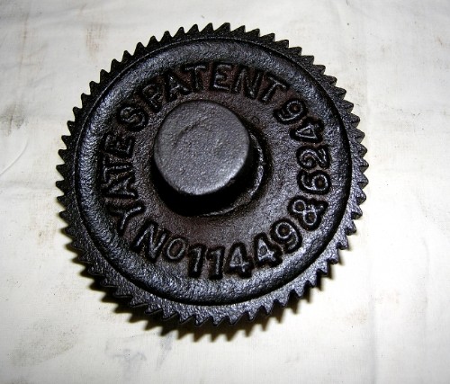
I was tidying the bench up and decided it was time this rusty bit of CI scrap was moved. It's a pattern for a bronze casting that I got when I was rooting through Kirkham's pattern store at Bolton before they closed. I have never looked at it properly and always assumed it was a pattern for the Wilby speed regulator ratchet on a Lumb Governor but noticed yesterday the name Yates on it. I think it's slightly more important. If I'm right this is the ratchet wheel for the speed regulator on the complicated governor that Yates (Predecessors of Yates Brothers and Yates and Thom) made for their patent sllde valve expansion gear. Before Corliss gears became popular a lot of engine makers experimented with complicated ways of making a slide valve that could have adjustable cut off to allow expansive working. The Jubilee engine at Masson has such gear and governor and could be the last one left, it's almost certainly the oldest Yates engine.
The thing that strikes me is the skill of the pattern maker who could cast a ratchet as accurate as this which was fit to be used as a pattern for making the final bronze version. The teeth would only need a bit of filing by hand to finish them off. So, a bit of scrap but one with a history. How do we preserve knowledge like this? How many people are left who could identify it? That's why I do my 'bleeding obvious' bits occasionally, what is obvious to us old farts may not be common knowledge. Far better to over-explain than assume everyoner knows.....
Now, about those crossheads!
Stanley Challenger Graham
Barlick View
stanley at barnoldswick.freeserve.co.uk |
Stanley
Local Historian & Old Fart
36804 Posts
|
|
Posted - 22/11/2011 : 06:55
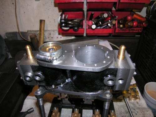
First thing was a very careful comparison between Mr Bahrett's design and my fag packet crossheads. No bad news, the relative position of the slides and the con rod pin centre are dead right, the problem was I hadn't got enough clearance between the top of the crosshead and the piston rod gland. Some carful measuring, checked twice and then some marking up!
Bottom line was that 5/16" had to be taken off the top surface. Still plenty of metal for the piston rod attachment so no foreseeable problems. Decision made, some serious cutting!
Stanley Challenger Graham
Barlick View
stanley at barnoldswick.freeserve.co.uk |
Stanley
Local Historian & Old Fart
36804 Posts
|
|
Posted - 22/11/2011 : 07:18
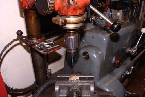
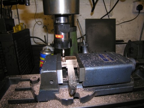
First job was to poke a 1/8" drill 5/8" deep to preserve the location of the piston rod attachment when the pop mark is milled off. Bleeding obvious tip, an easy way of drilling successive holes to depth is to put some insulting tape on the drill. You can get specialised drill stops but this way is quick and easy.
Touch the cutter up on the T&C grinder and then set up for a straight 5/16" reduction.
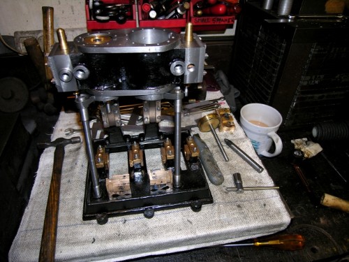
Close of play. All crossheads reduced, cleaned up and identifying numbers on the front face. Offered one up and problem is solved. 45 degree champher on front edge to accept the drilling for the oil hole to the con rod pin, this will be the first job this morning.
I have no doubt you have all been having a good laugh at me as I reduce relatively enormous blocks of bronze down to what we have here! I told you they'd get smaller! Nevertheless I am quite pleased with the result, If these were supplied as castings they would be a lot easier and in the process, my fag packet engineering has reduced the number of individual parts in the crosshead/piston rod from 10 to 2 and it will do exactly the same job. That pleases me.
So, oil holes and then some serious thought about piston rod attachment and measuring the correct length. Onwards and upwards! We get very close to serious swarf manufacture, the next job is to make two crankshafts!
Stanley Challenger Graham
Barlick View
stanley at barnoldswick.freeserve.co.uk |
Stanley
Local Historian & Old Fart
36804 Posts
|
|
Posted - 22/11/2011 : 09:39
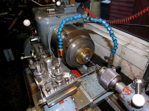
Don't expect this speed of service every day! It just so happens that I am having a correspondence with a man who has at least one of Johnny's epycycloidal chucks and I had to do a pic for him. While I was downloading them onto the Flying Machine I thought I might as well render these two.
First job was the oil holes. Here they are, popped a centre drill in first to give me a mouth and then drilled 1/8" into the bore for the pin.
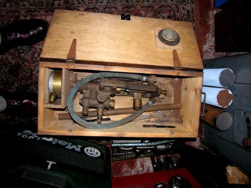
In order to answer my mate's question about the chucks I had to dig in the treasure chests and while I had this box out I did a pic for you just for interest. Brand new, never been used and destined for scrap, what we have here is a triumph of the brassfounder's art, a Vulcan Engineering hydraulic test pump for proof testing boilers. I say a triumph because the gauge with it is a steel tube Bourdon calibrated up to 10.000psi. Working on the usual 50% rule this means that this pump was made for pressures up to at least 5,000psi. Nothing but the best castings and closest work could give you these pressures. Part of a world long gone!
Right, enough laiking about. Back to the shed!
Stanley Challenger Graham
Barlick View
stanley at barnoldswick.freeserve.co.uk |
|
|
|
|