| Author |
 Topic Topic  |
|
Stanley
Local Historian & Old Fart


36804 Posts

|
|
 Posted -
29/07/2011
:
06:27 Posted -
29/07/2011
:
06:27
|
New start as old topic was getting too big. Here's the LINK for the original topic.
Sheds are centres of honest endeavour and sanity, rare things these days. Please join in and tell us what you are doing in your shed. All are welcome!
[By the way, if I occasionally seem to be stating the bleeding obvious, it's because I'm aware of the fact that not everybody has the same experience so please forgive me.]
Stanley Challenger Graham

Barlick View
stanley at barnoldswick.freeserve.co.uk
|
|
| Replies |
| Author |
|
|
Stanley
Local Historian & Old Fart
36804 Posts
|
|
Posted - 07/09/2011 : 05:33
Do you know Walter I thought about you yesterday and wondered whether you were keeping an eye on me. ESP is cheaper than phone calls! Be sure to criticise if you see me going wrong! Don't be jealous, just be glad that I was so lucky and that Johnny's stuff couldn't have fallen into better hands. I'm probably the only bloke in the world that knew the history, saw the opportunity and had the sense to grab it. That's the reason the man sold me the 1927 lathe for a knock-down price, he wanted it to stay in Barlick and be looked after and he trusted me to do it. He asked me what I could afford, I told him £150 and that was what I paid. A Kind Man with a sense of history. The reason why I post here is to do my bit towards preserving that history and the skills that went with it. My only regret is that I am not at your level of skill, I know my place! I once sold a Birch lathe to a bloke in the hills behind Hebden Bridge and when I went up to deliver it he was making a component in his Myford Super Seven. I looked at it and told him I hated him, I told him that when I saw a tool finish like that I felt like going home and scrapping the shed! He told me not to worry, he'd spent over 40 years in the toolroom and I couldn't be expected to be as good. He was right.....
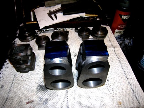
Close of play at noon yesterday. All the bottom lids are machined both sides and registered in the bores, Thicknesses checked and matched and all numbered and centred. They interfere with each other as they are at the moment but next job is a bit of rotary milling to match diameters with the top lids and when I have that done I'll know what I have to remove in the way of a flat on the diameter, if any, to make them match. They should just clear each other. I've found some scrap CI slabs that the lids can come out of.....
I'm giving a lot of thought to centre lines and matching the blocks up with the crosshead slides and journals. Not quite clear yet but the back of my head is working on it while I press on. To me, this is one of the fascinations of doing something like this. You have to re-invent what the old engine fitters knew by experience. I've always said that if you want to fully understand a steam engine you have to build one!
Stanley Challenger Graham
Barlick View
stanley at barnoldswick.freeserve.co.uk  |
Stanley
Local Historian & Old Fart
36804 Posts
|
|
Posted - 07/09/2011 : 06:23

It's a bit too early to go for the morning walk, too dark especially with a black dog so I thought I'd raise a point that has been on my mind. Mr Bahrett's 1922 engine has a flywheel and I have two 5 1/2" flywheel castings in the sets I had cast off Johnny's patterns. However, marine engines didn't have flywheels, they have a fitting on the end of the crankshaft which connects to the propeller shaft, often by a dog coupling which allows some flexibility in the alignment, ships change shape when in a heavy sea. However, some mill engines were marine type compounds and in that case had a flywheel because it was important for textile machinery to iron out the inherent cyclical variation in speed induced by four power strokes per revolution.
There is another consideration, as far as I can see the Bahrett engine has no reversing gear. Marine engines had them, textile engines didn't. The explanation could be that when Bahrett designed this engine for a friend it was intended to be used for dynamo driving in a home workshop. Remember we are talking about possibly 1915 for a design date and mains electricity was a rarity.
By an accident of history I'm building two engines so I am thinking of making one a marine engine for a Puffer because this gets me away from the complication of the air pump and condenser, and the other as a mill engine which needn't necessarily have the air pump and condenser integral with the engine, would have no reversing gear and would have a flywheel. I am shying away from using the surface condenser I have because I didn't make it. This has the added benefit that I would finish up with two different engines. I think I am favouring this at the moment.
This raises another point, I don't think I have ever mounted a flywheel on an engine shaft that completely satisfied me. The usual method is to use a plug fit and and one or two gib headed keys to fasten it on the shaft. This almost always puts the wheel out of truth. I have thought of several ways round this, turning the flywheel on the shaft or a dummy shaft etc. but have dacided that if I do fit it I shall make it a plug fit but not to the diameter of the shaft (1/2" in this case) but leave a larger boss on the end of the shaft which is almost an interference fit with takes to key it on. This was a mathod favoured by quite a few full size engine makers for flywheels and large second motion gears. I reckon I'll stand a better chance of getting a truly concentric fit. And yes, I might even make the stakes as dummies and Loctite the wheel on the shaft! Nowt wrong with cheating! Just the same fit as a shrunk-on crank so therte is an argument in favour of it.
Just an example of the way your brain wanders off into the tasks that have to be done and the reasons for them. It did cross my mind that I could sell one of the engines but I'd rather not do that, besides, who could afford to give me enough money to cover materials and time?
Stanley Challenger Graham
Barlick View
stanley at barnoldswick.freeserve.co.uk |
Stanley
Local Historian & Old Fart
36804 Posts
|
|
Posted - 07/09/2011 : 06:32
Just reckoned up. 44 days so far, average of four hours a day, Say 180 hours. Assume I'm half way through, so 180 hours per engine at £15 an hour to cover wage, depreciation expenses etc. Thats £2700 plus £700 for castings and materials which comes to a conservative £3,400 before any profit. Would you pay the thick end of £4,000 for a table ornament? I often think this way when I see antiques being sold. I ask myself how much it would cost to have the item made today. The prices at auction bear no relation. So I shall keep them both and let the kids fight over them! One thing is certain, nobody does anything like this for profit! It's a labour of love.
Stanley Challenger Graham
Barlick View
stanley at barnoldswick.freeserve.co.uk |
Invernahaille
|
Posted - 07/09/2011 : 22:27
In effect the rope drum on mill engines was the flywheel. Marine steam and motor engines run through a thrust bearing which houses a fly wheel
The angular velocity (radions) of a ships propellor and propshaft also serve as a form of flywheel.
|
Stanley
Local Historian & Old Fart
36804 Posts
|
|
Posted - 08/09/2011 : 07:01
Agreed Robert, that's what I did with the big marine compound I made from two Stewart VAs, it has what is in effect a small flywheel with an integral fitting for connecting the prop shaft. I made it so that it could be used for a launch engine but being two engines weded together is a big clunky beast unlike anything commercial. On mill engines even the geared engines had a heavy solid flywheel with a jack spur gear mounted on the side so as to get the dampening effect of the heavy rotating wheel. Ellenroad flywheel weighed 85 tons and that was rope drive on the periphery.
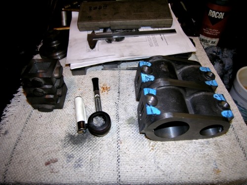
First job yesterday was to put a point on a piece of bright steel that exactly fitted the hole I had drilled in the top lids.
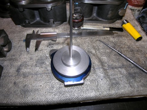
The pointer located with the centre drill pop in the bottom lids and I marked the rough diameter with the scriber. All lids marked with their matching opposite number.
All bottom lids drilled 3/8" to take the fixing screw. (The piston rods will be at least 3/8" so no problem there) Then all lids milled off wherever I could get at the diameter.
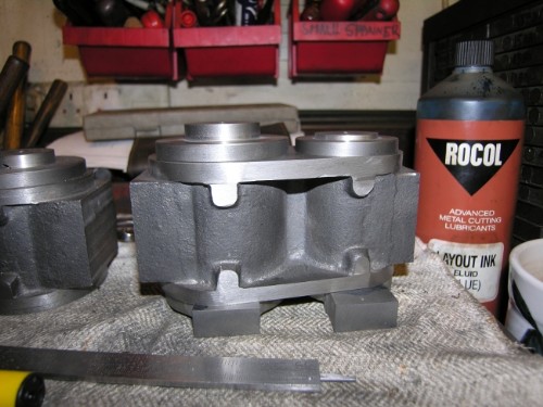
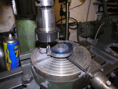
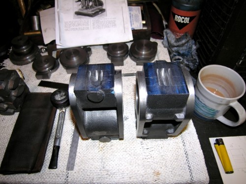
Once all the edges were milled, some careful filing dealt with the irregular surfaces. Here's what the rabbit looked like after the first pair were done. I've made the lids a bit thicker than Bahrett did. My rule of thumb is that they should be as thick as the cylinder walls. By the time I've finished this engine would stand 250psi easily.
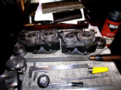
Close of play. I haven't filed the rough edges up on the left hand cylinder. I decided that while the rotary table was on the miller I'd mill a flat face on the bottom of the lids for the PCD of the holding down studs. The blocks are upside down of course. Made a few check measurements and by a miracle the lids are centred properly, the faces for attachment to the standards match the centre lines and the tabs for the support pillars are on the right centres. Even more of a miracle the levels of the attachments match across the two blocks. Not important of course, they are different engines but at least it shows some consistency, one of the advantages of building two engines together.
Today will start with filing the two bottom lids up on the left. Then I'll take a view. The only thing that is firm in my mind is that I am going to do all the fitting work on the blocks and lids before I get to the stage of addressing the attachment to the standards. I haven't quite worked out the stud arrangement for the attachment, it gets a bit complicated because the position of the studs for the lids interferes with the ideal position of the standard to block fixings. Plenty to do on the blocks yet, I think I might start with the steam ports and passages from the valve to the cylinders. Once these are done I will know what the size of the valve is and therefore how much room I need in the steam chests, thay are still in their rough state. One thing is certain, I shan't be using Bahrett's method of multiple small holes drilled from the outside and then plugged afterwards. Some commercial castings have the steam passages cast into the body but of course I'm starting from the solid. I shall use the Newton Pickles method! It has never failed me yet. Onward and upward! I like this stage, it's beginning to look like an engine, you can see the finsished shape. It always surprises me how big the cylinders are compared to the beds.
Stanley Challenger Graham
Barlick View
stanley at barnoldswick.freeserve.co.uk |
Gugger
|
Posted - 08/09/2011 : 17:07
Stanley, it is a privilege to be able to look after such beautiful equipment. But at our age it can become also a burden once you start thinking about its future. The generations after us don’t have the knowledge, interest and skills to see the value in such pieces to worship it as we do.Regarding skills, we won’t argue about that. With your background and what you have achieved in other fields, looking at your running project, I will say as the French do, chapeau. Walter
|
Stanley
Local Historian & Old Fart
36804 Posts
|
|
Posted - 09/09/2011 : 06:39
You're right Walter of course but that's their problem not mine.
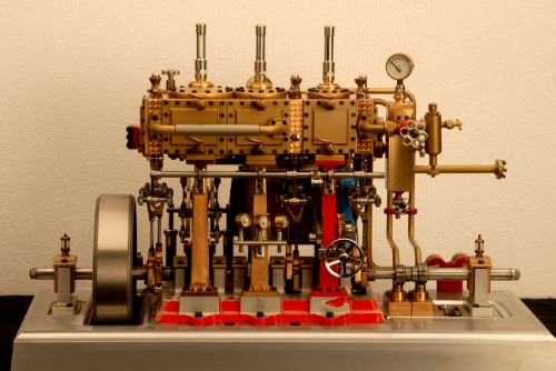
Remember the Bloke at Hebden Bridge? Walter's mate Hans is making a marine engine. Here it is. See what I mean about levels of detail and skill. Bloody sickening! Makes mine look positively 19th century. (Which of course is what it is). I told you I was just a bum fitter!
Stanley Challenger Graham
Barlick View
stanley at barnoldswick.freeserve.co.uk |
Stanley
Local Historian & Old Fart
36804 Posts
|
|
Posted - 09/09/2011 : 08:09
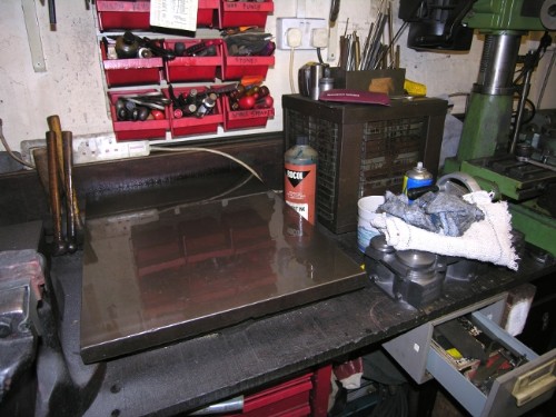
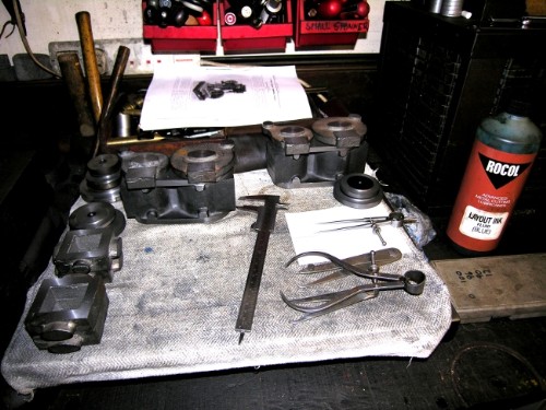
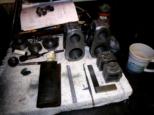
All right, I'm obsessive about cleaning up! I had a good clean up, washed the dirty table cloth and laid a new one. I always spray the surface plate with WD4o or similar when I clean it. If you don't, you'll find rust on it when you need it! I can hear Newton laughbing at me!
All nice and tidy. Blue the HP valve faces and a bit of careful marking up after reminding myself of valve port positioning. Then measure at least twice and keep checking you have it right. Once these are cut you are commited! Worst mistake I ever saw was perfectly measured and marked ports, carefully cut and then Bugger! wrong orientation! (No, it wasn't me)
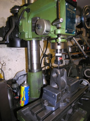
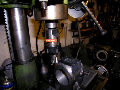
Set the Jones and Shipman vise up square on the bed. Put a 1/8" slot drill in, check all the measurements for the last time, clearly mark what you are going to cut out and then get going! A 2hp motor driving a 1/8" cutter takes no prisoners! So carefully away, no big cuts, patience and vigilance. Don't get distracted! (What did the old lads do before the days of accurate slot drills?)
Close of play. Later than usual, I had a rush of blood to the head and decided to finish the ports before stopping. All the ports cut reasonably accurately and in the right place. Not a bad day and a straight edge!
Stanley Challenger Graham
Barlick View
stanley at barnoldswick.freeserve.co.uk |
Stanley
Local Historian & Old Fart
36804 Posts
|
|
Posted - 09/09/2011 : 14:28
There will be no work in the shed tomorrow, I shall be preserving my strength ready to act as guide to a group of extreme Brierfield genealogists.
The purists are going to hate this! I've poked a 1/4" drill through from the bore to the steam ports on all four cylinders. No slip ups, a clean entry into the port each time after a lot of measuring up and angle finding. This is the Newton Pickles method and I remember the first time I saw him do it I was aghast. I asked him about the way the port hole in the bore extended down the cylinder due to the angle. He told me it didn't matter as it stopped before it reached where the piston ring was at the end of the stroke. He pointed out that when he was boring cylinders he always made them bell-mouthed and the end of the cut ended midway on the nearest ring. The reason for this was so that the ring didn't wear a step on the bore, when it finished the stroke it was partially hanging over the bell mouth. So, the fact that the port extends down the bore doesn't matter. That's my story and I'm sticking to it! One tip, start the steam passage by cutting an inclined flat with a slot drill, this means the drill will get a clean start and not tend to wander.
Stanley Challenger Graham
Barlick View
stanley at barnoldswick.freeserve.co.uk |
Stanley
Local Historian & Old Fart
36804 Posts
|
|
Posted - 10/09/2011 : 06:28
Not a lot will be done today as I need to conserve my energy for the Militant Tendency of the Briercliffe Genealogists! Checked up in the shed last night and yes, I was right, I have plenty of 1/2" OD copper pipe. Scales up nicely for the exhaust piping. I like the old threads and 26tpi brass thread has always been a favourite so a 29/64" drill could be poked into the castings to reach the exhaust port this morning. Main reason for doing this is that this is the end of major cutting on the block so I can put that behind me. Always a bit worrying because any errors are virtually terminal! Nothing looks worse than a wrong hole that has been plugged and re-drilled!
I've been thinking about valve rods before I start maching the steam chests. I have always followed Newton's practice of extending the top end of the valve rod into a blind brass guide to make sure the rod can't wander when it gets worn. Bahrett has a gland for this purpose but I've never understood the reasoning behind this, very common in full size practice but a blind guide does the job and of course no possibility of leakage or another tiddly little packing that needs adjusting. Another Newton trick I like is to make the adjustable part of the gland as a plug threaded into the casting and adjusted by tommy bar holes round the periphery. Far better than fiddly little nuts and studs. They have another advantage, they are always square to the rod when tightened, ordinary glands can tip if you aren't careful to tighten them evenly. So, steam chests and lids from Sunday onwards!
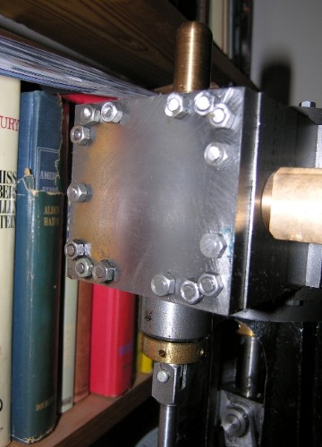
Here's the LP lid on the big compound I made. You can see the tidy glands and the blind guide on the top for the end of the valve rod. If you look carefully you can see the same packing nut inside the standard. Imagine trying to work on that one with little spanners and hardly any access. Using a tommy bar is dead easy.
Notice also the bloody mess I made by putting that extra nut in the corners of the lid! We all do things that seem like a good idea at the time but with hindsight are bloody awful! One of these days I'll take the lid off and put this right...... Don't be too hard on me, we all do things like this. I have a traction cylinder block that newton made when he was a lad and he made exactly the same mistake. Johnny played hell with him and so Newtom threw it into the scrap box. I might do you a pic.....
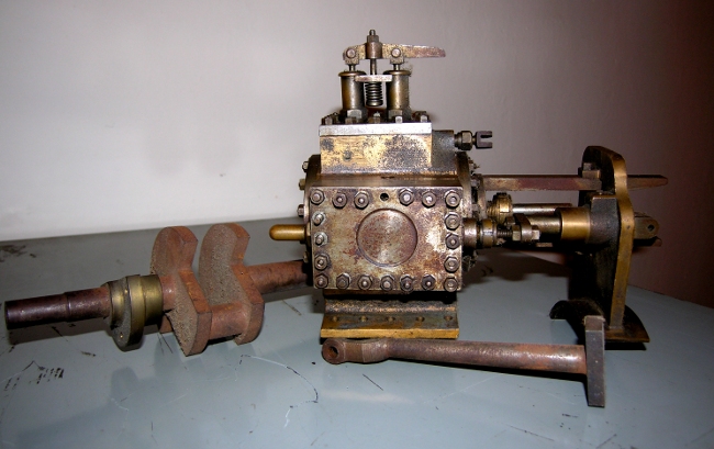
Here's Newton's 1935 mistake. Look at the work he'd put in on it. Notice also that even then he was using blind guides and one piece gland nuts.
Stanley Challenger Graham
Barlick View
stanley at barnoldswick.freeserve.co.uk |
Stanley
Local Historian & Old Fart
36804 Posts
|
|
Posted - 10/09/2011 : 09:58
Couldn't stay out of the shed, decided to get a straight edge.
Last part of the valve ports was to get the exit holes drilled and tapped. First stage was a bit of careful measuring up of course, some marking and a ventre pop. Then poke a 3mm drill through into the valve ports, if that's nicely in centre, drill for the exhaust pipes with the 29/64" drill on the VM for rigidity and accuracy. Then back under the pillar drill and poke a 1/4" drill through into ther valve ports.
Then dig out the intermediate and plug 26tpi 1/2" taps. A bit of careful tapping and Bob's your uncle.
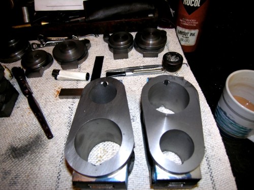
This was close of play at 9:30, both blocks complete with valve ports, steam passages and tapped holes for the exhaust. Then I decided to get rid of the layout ink by wire brushing it off. Now I've mentioned this before and it's worth another outing. I have never heard of anyone sharpening a wire brush but I did it one day and discovered what a wonderful improvement it was. I can't be sure but I think I re-invented this, I can't believe that someone else hasn't done it but if they did they kept quiet. All you do is drag the brush backwards over a grinding wheel (on speed obviously) and this puts a sharp edge on the leading edge of the bristles. Try it, I promise you'll be amazed at the improvement, particularly good on brass if you're cleaning old fittings up.
The castings are now clean and can sit on one side for while until the steam chests and lids are ready for fitting.
Stanley Challenger Graham
Barlick View
stanley at barnoldswick.freeserve.co.uk |
pluggy
|
Posted - 10/09/2011 : 10:09
Probably get verbally lynched as a heretic for this, but wouldn't hex socket headed bolts make sense for the steam chest lid ?
You can put plenty of them in without worrying about getting a spanner to them.
Need computer work ?
"http://www.stsr.co.uk" 
Pluggy's Household Monitor |
Stanley
Local Historian & Old Fart
36804 Posts
|
|
Posted - 11/09/2011 : 06:47
Dead right Pluggy and of course that's what Walter's mate has used but old engines look wrong to me with hex head screws. Mind you, I have been known to use a hex head grub screw to lock a shaft but of course they were buried. Bancroft engine was built 1914-1920 and Roberts used a big hex head set screw to lock the governor rope drive pulley on the flyshaft. Not the modern HT one but same principle. The only one on the engine.
Tiring day yesterday so an easy day today. Might start tidying the steam chests up.....
Stanley Challenger Graham
Barlick View
stanley at barnoldswick.freeserve.co.uk |
Stanley
Local Historian & Old Fart
36804 Posts
|
|
Posted - 12/09/2011 : 06:56
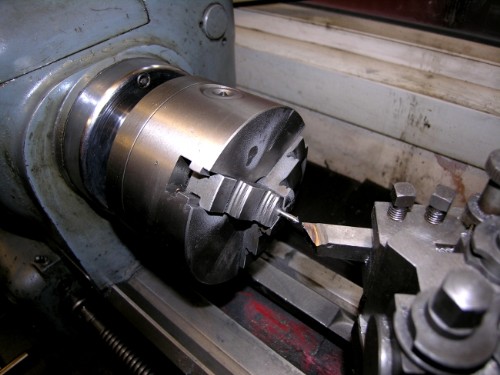
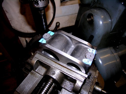
I decided the first job was to tidy up the face of the valve ports. Sharpen a cutter, get set up square and take the merest skim off the faces to get rid of the scribing marks and make sure the faces were flat and square to each other.
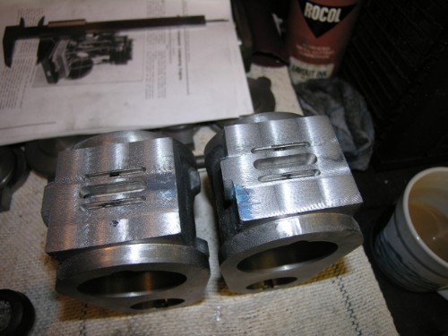
The end result, both faces fead flat and square to each other. You can see how little has been taken off by the fact that some of the layout ink still survives. This will go when the final clean up is given to the face by rubbing down the faces on very fine emery on an old surface plate to get a fine ground finish. That will be the last job before assembly.
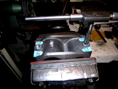
Next job was to attack the steam chests. I already had two parllel sides machined on them. First job was to file the internal surfaces of the chests and as I did them I reflected that for a bloke that was reckoning to have an easy day I wasn't half working a sweat up! No matter, after an hour I had clean surfaces. Actually the engine would work just as well if this wasn't done but it makes them look so much better, easier to do a close fit of the valves and makes sure that there are no traces of castng sand or loose casing skin to contaminate the chest. I always remember Newton having a lot of trouble with the new LP cylinder at Crow Nest whan they started it after repair. A pocket of casting sand in the steam cavity came loose and dropped in the cylinder. Not good, the cure was to take the lid off the steam chest, pour 20 gallons of cylinder oil in and let the oil swill the sand out of the bore. It worked.No big pockets of sand here but we are looking for s lttle contamination as possible.

Close of play at noon. Valve faces done, all steam chests cleaned inside and some sides milled square and parallel. This morning will be finishing the valve chests to fit the valve faces and sorting out the material for the lids. This is a nice stage because after a lot of work on the blocks and castings you suddenly realise that you are getting close to stud fitting and valve making. The end is not yet in sight but we are a long way down the road and the magic of the shed is getting near to producing two working engines. Lovely stuff and very good for me! Notice that I am on the same course as newton was when he was making the traction engine cylinder above. Get the cylinder assembly finished before you start to address the union between it and the rest of the engine. Good to tell who taught me!
Stanley Challenger Graham
Barlick View
stanley at barnoldswick.freeserve.co.uk |
Stanley
Local Historian & Old Fart
36804 Posts
|
|
Posted - 13/09/2011 : 05:23
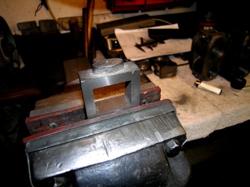
Close of play yesterday. All the steam chests squared up, centred for drilling and all faces finished except for the bottom where the valve rod gland will be. I cut the top bosses off as I don't need them for the blind valve guides. Must have a look at valve rod sizes etc before I go any further. All the cutting done on the VM but the bottom face will be in the lathe as I want a tidy round boss for the gland. The casting sizes in relation to the faces has worked out well. I haven't milled the sides of the cylinder block casting as it's clean and the right size. Slow but sure progress. You always tend to forget how much work goes into these little bits, ten faces on each steam chest that need attention (not counting the boss faces)! Four chests, so forty measurements and set-ups. Makes you realise why more engines aren't made!
Stanley Challenger Graham
Barlick View
stanley at barnoldswick.freeserve.co.uk |