| Author |
 Topic Topic  |
|
Stanley
Local Historian & Old Fart


36804 Posts

|
|
 Posted -
29/07/2011
:
06:27 Posted -
29/07/2011
:
06:27
|
New start as old topic was getting too big. Here's the LINK for the original topic.
Sheds are centres of honest endeavour and sanity, rare things these days. Please join in and tell us what you are doing in your shed. All are welcome!
[By the way, if I occasionally seem to be stating the bleeding obvious, it's because I'm aware of the fact that not everybody has the same experience so please forgive me.]
Stanley Challenger Graham

Barlick View
stanley at barnoldswick.freeserve.co.uk
|
|
| Replies |
| Author |
|
|
Stanley
Local Historian & Old Fart
36804 Posts
|
|
Posted - 06/11/2011 : 06:58
PS. You'll almost certainly find that when all the studs are tightened up the chest shifts slightly and you lose the perfect fit between the chest and the block that you arranged when you made the parts. If you want to avoid this enlarge the holes in the lid and chest so that the fit is sloppy and you can clamp to position before you tighten the studs. Personally I like the chest to be solid and so the fit drifts a bit. It doesn't worry me but you might want to consider this. Of course if all my markings were dead accurate this wouldn't happen but as you know, I'm a Bum Fitter!
Stanley Challenger Graham
Barlick View
stanley at barnoldswick.freeserve.co.uk  |
Stanley
Local Historian & Old Fart
36804 Posts
|
|
Posted - 06/11/2011 : 07:23
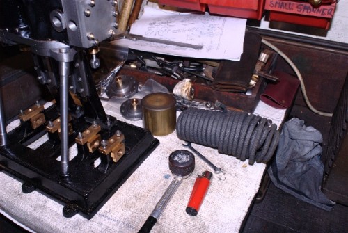
Scrub the last request! There is a providence that looks after drunken men and Bum Fitters. After I had logged off I had a sydden thought and went in the shed to have a look in the Dremel box. It doesn't get used very often, it's one of those tools that sits there on the shalf waiting for the time it can get you out of trouble.
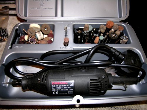
If you look carefully just above the section marked 'collets' in the centre you'll see a small grinding head with a curved face in the centre. I think this is just the very thing! Writing the request must have triggered a long disused synapse somehere in my brain. Thank You God!
Stanley Challenger Graham
Barlick View
stanley at barnoldswick.freeserve.co.uk |
Stanley
Local Historian & Old Fart
36804 Posts
|
|
Posted - 07/11/2011 : 05:58
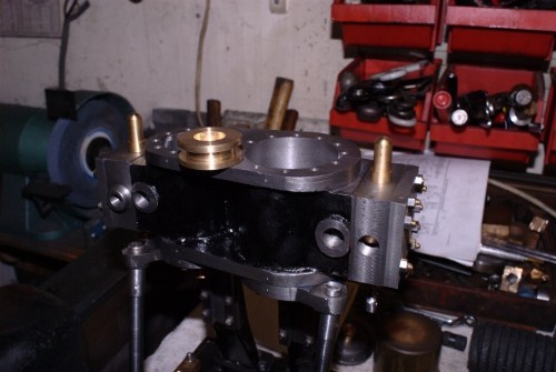
A day of small but significant things.
The steam chest suds after a bit of attention with the Dremel. All lids done and dusted.
Here's a small matter that had been nagging me. The flange on the end crank brass was restricting the space in the bed for the eccentric. Sharpened the milling cutter and milled the flange down on both engines to give me as much room as possible in the aperture. Remember that this eccentric will be one of the locators to control end float in the crankshaft.
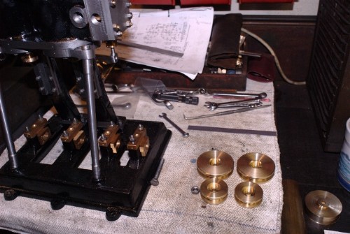
Pistons. As I mentioned earlier I am making these engines with compressed air driving in mind and will use graphite/asbestos packing instead of piston rings. Read LBSC on early steam locos and you'll find that this was common and perfectly good practice especially in bronze cylinders. My cylinders are CI of course but I have bronze bar running out of my ears so I went upstairs and found some stock. Another advantage of this is that their will be minimal wear on the bores and if anyone wants to replace the pistons with CI and rings they'll have perfect polished bores to fit to! So, that's the pistons catered for.
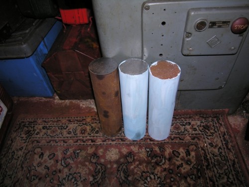
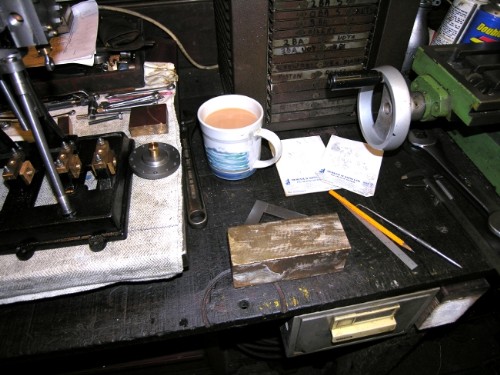
Stock was on my mind so I took ten minutes to give the shaft blanks a coat of layout fluid ready for marking up. We are very close to crankshaft turning and it's a job out of the way. Notice I have a spare in case I cock up!
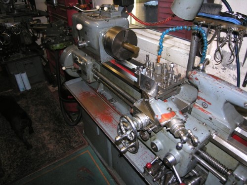
Attention then turned to pistons. First job was to give the Harrison a good clean up so I can harvest the non-ferocious scrap (Sorry Lads!) in clean condition. Nothing encourages good work better than a clean lathe! Then I got Johnny's old 7 1/2" Belco chuck out. I only have the outside jaws for it but it has a centre hole big enough to take the 1 1/2" bar that the pistons will be made of so I can rurn without using a centre. This old chuck isn't accurate but still useful. I think you might be able to see a yellow spot on the bronze bar. There is also a yellow spot on the adjacent jaw. If for any reason you have to take the bar out of the chuck you can put it back in the same position and preserve concentricity of the new cut. I don't think I will have to do this but not a bad thing to be prepared.
It was getting on by this time so I decided not to start on the pistons but have a good vacuum and clean up. All right, I could hear Newton laughing but cleanliness is next to dirtyness and I am sure I do better work when all is tidy, it's the way I was brought up!
All my ducks are in a row and we have a straight edge. Programme now is make the pistons, rods and crossheads. Then, before we make the motion we have to get a crankshaft to measure from. Things are coming together! Very satisfying. Didn't give a thought to the economy all morning!
Stanley Challenger Graham
Barlick View
stanley at barnoldswick.freeserve.co.uk |
Stanley
Local Historian & Old Fart
36804 Posts
|
|
Posted - 08/11/2011 : 06:41
First job was to have a dig in the packing box to make sure I had some 1/4" packing. This triggered me into displacement activity (I am easily diverted!) and I finished up doing a bunch of housekepping like dressing the grinding wheel, sharpening the 1/4" drill, finding a milling cutter for the recess in the piston for the nut on the end of the rod, sharpening that cutter and then finding a drill chuck big enough to take the cutter (you can't have too many chucks!). Then vacuum up all the muck frm dressing the grinding wheel! (I covered the bench with a cloth while I was doing that, grinding wheel dust is a bugger in the wrong place). All this took time but I soon knocked off the first HP piston and then came to my old bugbear, parting off.
I don't think anything has caused me as much grief as parting off. I have broken more cutters than you can imagine. I am crap at it. However....
When I bought the Birch lathe one of the tools that was with it was this Burnerd Parting Tool Holder. They aren't made today but there will be old ones out there somewhere. If you find one clasp it to your bosom and never ever part with it! I think you can see how it works, the top arm is set to the diameter and restrains the tool from hogging which of course is what causes the problems. It is a complete answer, beautifully made and I promise you'll never avoid deep narrow cuts again!
I always remember being at Dixons at Worsthorne buying the Harrison lathe. They had a big useful Dean Smith and Grace lathe for sale and a prospective buyer had come down to test it. They wired it up and he put a piece of 6" stock in the chuck and the biggest parting tool in the world in the toolholder. It must have been 1/2" across the face and about three inches deep. He set the lathe on at a lowish speed, set the drive on auto and sent the parting tool straight into the stock. Blue chunks of swarf smoking out of the cut and straight through. As I stood there in awe of this superman he turned round and said "There's a coil down in the motor, have it rewound and I'll take the lathe". I've never forgotten him, even Newton was impressed (he was with me making sure I didn't make a fool of myself) That bloke knew about parting off!
So, only one piston at close of play but I'm set up now and the others won't be a biggy. And yes, you're right, there will be more packing than piston! I have made it sloppy in the bore, probably 1/32" clearance, but this doesn't matter, the packing is doing the sealing, not the piston. Incidentally, Bahrett's design calls for a 1/4" ring same as my packing. You could run this engine for years and only polish thebore.
Stanley Challenger Graham
Barlick View
stanley at barnoldswick.freeserve.co.uk |
belle
|
Posted - 08/11/2011 : 23:39
I'm liking the pink hearth rug..where did you get it?
Life is what you make it |
Bradders
|
Posted - 09/11/2011 : 00:37
Bit of carpet ...more like...
Helps to stop your feet getting cold ....eh !
BRADDERS BLUESINGER |
Stanley
Local Historian & Old Fart
36804 Posts
|
|
Posted - 09/11/2011 : 06:51
Belle, I've always had carpet in the workshop. Hangover from carpets in engine houses. Kinder on the feet, warmer, easy to vacuum and if you drop something delicate it stands a better chance! The carpets are odds and ends I have begged at one time or another.
Stanley Challenger Graham
Barlick View
stanley at barnoldswick.freeserve.co.uk |
Stanley
Local Historian & Old Fart
36804 Posts
|
|
Posted - 09/11/2011 : 06:56
Not a lot to report. All four pistons finished and ready for fitting. I'll make the rods today but slightly over length and plain ends as I'm not following Bahrett. His crossheads are too complicated. I'll decide on the design when I come to them!
Stanley Challenger Graham
Barlick View
stanley at barnoldswick.freeserve.co.uk |
moh
|
Posted - 09/11/2011 : 11:08
You'll have to get some steel toe capped sheepskin slippers Stanley!!
Say only a little but say it well |
belle
|
Posted - 09/11/2011 : 13:49
I always wondered who the Carpet Beggers were..seems like Stanley was one of them!
Life is what you make it |
Stanley
Local Historian & Old Fart
36804 Posts
|
|
Posted - 10/11/2011 : 06:40
Moh, I never wear slippers in the shed, the soles are soft and pick up little bits of metal and you have shiny things in the carpet in the house. I remember Newton once telling me about the trouble he got into with his mother when he was turning brass on his lathe in the attic. Brass tends to come off as tiny chips and gets everywhere!
Belle, all carpet fitters have old pieces of carpet that they have to send to the tip. You'd be amazed how good some of them are.
Nice to see you both looking in. I don't understand this technical and non-techical bit. I see poetry and sculpture in shaping metal and what's more, an engine is a mobile sculpture when you set it going! You take dead metal and give it life!
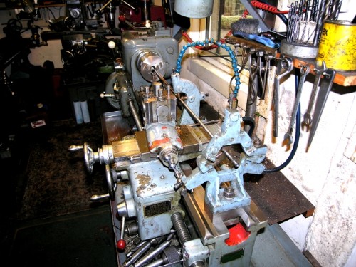
Not a lot to report yesterday as I allowed myself to be diverted so I could show a technique on the lathe that doesn't often get an airing. The task was piston rods and I had no 3/8" bright bar so I had to make some out of 7/16" stock. Normally I'd simply cut the stock to length and then turn to size but yesterday I decided to turn the whole bar down to size in one go.
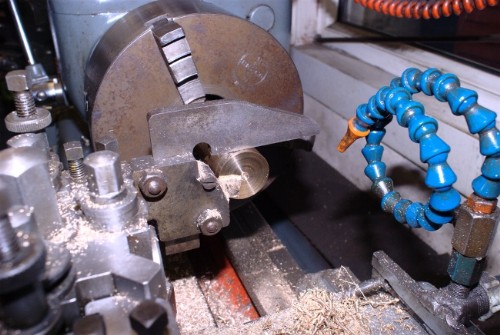
Anyone who has done it knows that when you have a long lenth of relatively thin stock in the lathe it's impossible to turn it accurately to size because it deflects under the pressure from the cut. The answer is a travelling steady. If your lathe has its full complement of accessories you'll have one.
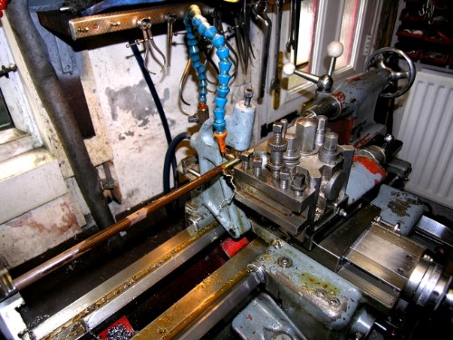
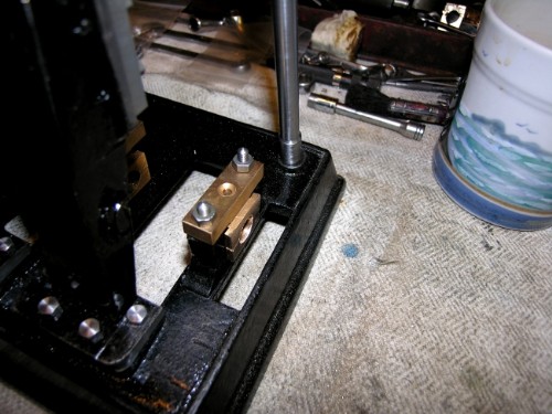
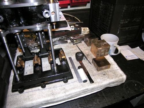
I think you can see the idea. The steady is bolted on the saddle and supports the stock with two copper plugs that can be adjusted. You only need two because the cut tries to lift the bar and force it backwards and these movements are restrained. Tail stock centre takes care of the back end and away you go. However, if it's a long bar....
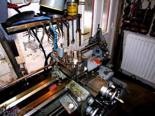
You have to take the tail stock off the bed and substitute the fixed steady. Adjust the three steel rubbing jaws to restrain the stock without gripping it. It's what it says on the tin, a steady. Here's another view of the set-up.
Sometimes with a long thin bar you can get a chatter starting up as the bar resonates under the cut. Daft as it looks you can damp this by simply hanging a piece of cloth on the revolving end or simply resting your hand on it. End result was a piece of bright bar near enough to 3/8".
All this took time because I had to clean the stud holes out in the saddle, find the correct cap screws and get everything cleaned up, I haven't used the steadies for years. However, I thight it might be a good bit of bleeding obvious for anyone who hasn't used the steadies.
Thinking about the function of the travelling steady and why it only needed two jaws reminded me of something connected with parting off. All cuts generate lift on the headstock spindle. If you're lucky enough to have a good tight lathe this isn't normally a problem. Parting off is extreme cutting and generates more lift than any other cut. If you think about it, the slightest lift generate hogging and before you know where you are you've got a jam, a broken tool and a ruined workpiece. We've all had them if we admit the truth!
On the old fashioned lathes like Johnny's you could give the front bearing on the headstock a bit of a nip to tighten it up but with modern roller bearing heads you can't do this. A lot of turners use an old trick. Mount the parting tool on the back of the saddle upside down and cut away with reverse feed on the cross slide. The pressure of the cut is reversed and tries to push the headstock bearing down where, no matter how worn the bearing, there is no play. Have a look at your lathe and you'll almost certainly find a stud hole or two that have no obvious use. You might even find a special toolholder amongst the bits that came with your lathe. I've never tried it but they tell me it works like a charm! It could make an impossible cut practical.
Enough playing out! Piston rods today.... Or should I grind them to a perfect finish with the toolpost grinder as another bleeding obvious demo?
Stanley Challenger Graham
Barlick View
stanley at barnoldswick.freeserve.co.uk |
Stanley
Local Historian & Old Fart
36804 Posts
|
|
Posted - 11/11/2011 : 06:42
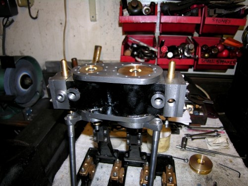
This was the story yesterday. All the rods fitted to the pistons and installed.
However.... Remember me saying that I wasn't impressed by the alignment of the LP cylinder on No. 2 engine? It became obvious when I fitted the piston and rod that there was something sadly amiss, it was well out of line. Not displaced sideways as I first thought but not running parallel with the bore. A word of advice. When something like this happens don't panic and start doing radical alterations, think carefully and logically. It can't be the bore out of parallel, you made sure of this when you set the block up for boring. Because I have made the pistons deliberately sloppy and the rods a good fit in the glands, the problem is going to be in either the central drilling in the bottom lid or the gland itself. I shall do a proper investigation this morning and find the cause. One decision I have already taken is to reduce the rods from 3/8ths to 5/16" as in the original design. Apart from the fact that they look a bit heavy for the size of the engine, this is no detriment because the seal is the packing in the gland nut and this will accommodate the reduction easily. The bore centres are, as far as I can see, just about perfect, all directly in line with the crosshed slides and this is the important thing. I shall have a good study this morning and report later! No despondency! These things happen, it's called fitting. All we need is a workable solution!
Stanley Challenger Graham
Barlick View
stanley at barnoldswick.freeserve.co.uk |
Stanley
Local Historian & Old Fart
36804 Posts
|
|
Posted - 12/11/2011 : 05:44
No pics today, I got so engrossed in my little puzzle I forgot to take any. If I had you would have been impressed! After all my strictures about not taking drastic action I sorted out a 25/64" drill, put the engine on the VM bad and poked the drill through the hole in the bottom lid, that meant I knew that it was dead vertical and centred. (The El Cheapo VM has a good height on the head! Those Taiwanese designers knew what they were doing!) The hole was very slightly off centre. Then I turned the rod down to a shade over 5/16" with the best finish I could get and did the HP rod as well. I also checked the centres of the two cylinders and they were as near 2 3/4" as makes no difference. All this means the engine will run nicely, everything is parallel. However, the LP is slightly off centre to the crosshead guide so I know now where the problem arose. The LP standard is slightly out of synch with the LP bore centre line. The cure for this is to strip the engine down, plug six tapped holes, redrill and tap and that will make it perfect.
However, you won't be surprised to hear I am not going to do that. I shall make the crosshead slightly off-centre to accept the discrepancy and it will run OK. A drunken man on a galloping horse won't see the difference! It will make no difference to the journal position on the crankshaft. All right, I'm lazy but I'm too old to bother too much about these things! The rods on the No. 1 engine are perfect but now I have taken the rods on No 2 down to 5/16ths they look much more in keeping so I'll do the ones on No 1 as well first thing this morning.
Next job is to work out how I am going to make the crossheads. At the moment I'm leaning towards chopping them out of a lump of cast Aluminium Bronze I have in the treasure chest. Tough stuff and it will never wear out! Won't need bushing for the crosshead pin either. (If ever it does wear it will be a simple matter to bore and bush.)
The overall message for anyone new to making engines is that these things happen and can be the most interesting part of the job. Finding the problem, deciding what to do about it and also making quite sure what your eventual goal is. If it's perfection for an exhibition, do the strip down and rebuild. If it's simply to have an engine that runs well, go down my road. Every full size engine I have ever run has had manufacturing faults, some of them quite serious but what the old fitters did was work round the problem, all they wanted was an engine that would do the job, they weren't entering them in a competition! Besides, what else would you expect from a self-confessed bum fitter!
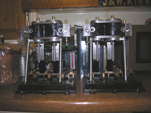
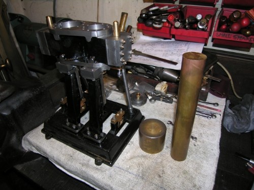
I did a pic for you of close of play. Due to perspective all the rods look to be off centre but take it from me they're OK except for the right hand LP and that is nowhere near as bad as it looks like in the pic. I think you can see that the thinner rods look better.....
Stanley Challenger Graham
Barlick View
stanley at barnoldswick.freeserve.co.uk |
Stanley
Local Historian & Old Fart
36804 Posts
|
|
Posted - 13/11/2011 : 06:17
First job was to skim the piston rods for the No 1 engine. Bleeding obvious bit... This is where the Mitutoyo digi vernier that you'll occasionally see lying about on the bench comes in handy. Get the equivalent measurement for 5/16" , dial it into the vernier, zero at that position, measure the rod and you'll get the difference between what you have and what you want. Divide by two. Gently put the tool in contact with the work, zero the cross slide dial, then back off the dial by whatver the digi vernier told you the cut was. Traverse the tool to the start of the cut, advance the cross slide to zero on the dial and get cutting. In this case it was about .022" of cut and the result is 5/16". Simples!
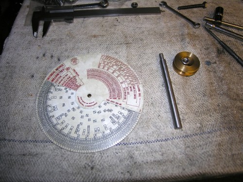
While I was doing this I automatically reached for my DTC rotary chart. It's the easiest way of converting values and a lot of other things as well. I don't know if they are still made but if you see one, grab it. Far quicker than books of tables or wall charts. Rods attended to, a nice sloppy fit. Don't worry about this, the packing in the gland and the piston will sort all that out and you'll have a nice free-running engine.
On to the crossheads. I had to work out the design and do sme careful measuring to get the size of the block I was going to chop them out of. Probably best if you follow Bahrett's complicated little design rather than my material hungry way! I don't know what a block of cast bronze would cost these days, it just so happens that I have enough to last me till I die. One of the advantages of a lifetime of collecting and old age! When I looked at the pic the lovely oily finish of the wooden bench top struck me. What Arthur Negus called 'the patina'. You can only get that finish after years of wiping down with an oily rag. When Newton moved out of Vicarage Road to his little shed in the backyard at Damside Cottages he hadn't room for the big bench he had inherited from Johnny and so he gave it to me. Johnny was a man of quality and the boards are 10" x 1 1/2" solid mahogany, hard as the hobs of hell! The legs and cross-pieces are mahogany as well. It's a solid bench and a joy to work on. I don't know about you but I can't stand a bench that rocks! (Best bench I ever worked on was at Rochdale Welding. It was a piece of 3" thick boiler plate 12ft x 6ft mounted on six legs made of 9" heavy walled steel pipe. If you were working on a big steam valve you could weld set screws to the bench top and bolt it down. Grind the welds off afterwards of course so you always had a level bench!)
Enough of that, we have work to do!
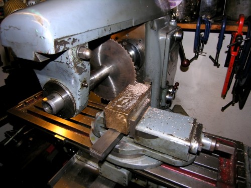
No surprises here. The big slitting saw in the HM and the block was sliced into 7/8" blocks. I sliced the fag end as well so that the surplus bits were clean and square ready to go back in the treasure chest. Big advantage apart from the saving in time (imagine sawing these by hand!) is that all the faces are dead parallel, a good start when you want to square them up.
Four nice slices of bronze. A Good start. They look big don't they! Don't worry, they are going to lose weight!

You won't be surprised to hear that I had a good clean-up. Harvested the non-ferocious milling chips and put them in my new scrap bin courtesy of the Council stopping collection of food waste! Then popped the milling cutter into the Clarkson T&C grinder and made sure it was sharp. ( I think the grinder cost me £600 and at the time I wondered whether it was just a vanity buy but over the years I have realised that it makes all the difference to your milling. If you see one lying abpout and you have some cash in your pocket grab it. You'll never regret it.)
Then a bit of milling. No sizes at this point, all I want are square blocks that can be measured and marked accurately. I got one block squared before close of play. Tomorrow's work is set out for me.
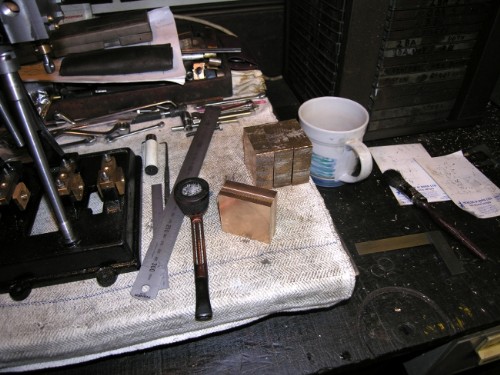
It strikes me, and I don't know whether you agree, but years of working with accurately made machinery seems to educate the eye. I only have to glance at this block to be fairly sure it's dead square. One thing is certain, any discrepancy leaps out and hits you in the eye. I don't know if you are born with this or not but whatever the origin I think I've developed it over the years. I'd be interested to hear your views on that one.
Stanley Challenger Graham
Barlick View
stanley at barnoldswick.freeserve.co.uk |
Asquith
New Member

23 Posts

|
|
Posted - 13/11/2011 : 10:07
It would be interesting to hear of examples of machining errors on full size engines. The bigger and more affluent makers could afford to work with the machine tool companies to make life much easier - buying machines to tackle as many locations as possible without disturbing the component.
I was reading yesterday about a big planing machine by John Hetherington of Manchester in 1883 for Musgrave’s of Bolton. It could take components up to 10 ft wide and 10 ft high and had a 30 ft stroke. Importantly, it could also plane crosswise, so you could machine faces square to other faces (as long as the machine stayed accurate).
Then the wonderful Kearns and Richards horizontal borers came along.
Some firms, Tangye for example, had machines with various drilling/milling/facing heads that came at an engine’s bedplate from all directions, making the holes and faces nice and parallel and square while the component just sat and waited.
The paupers and dinosaurs in the industry were probably better off sticking to old engine designs, with simple bedplates and separate bearing pedestals and crosshead guides, and some good fitters who could chip and file and align things. All done with the minimal of measuring equipment, no clocks, etc.
Since I returned to model steam engine making, inspired by this thread, Mrs Asquith has got used to my frowns and despondency after I’ve made yet another mistake, but I’m able to point out that there aren’t many mistakes that can’t be rectified - somehow.
I do run into many difficulties, mostly of my own making. Some are down to basic stupidity, others are due to incompetence or undue optimism about the accuracy of milling vices, etc. However, one area where I feel blameless is in drilling hoes through covers. I take the greatest care in setting up, then starting with a stiff centre drill, etc. but in the end not all the holes in a group line up perfectly. I think part of the trouble is that the size of drills we use in this work means that they are flexible and ready to wander off, especially if they’re not perfectly ground. As for drilling the evil phosphor bronze with ordinary drills…..
I’m also the world’s slowest machinist. Wondering where the time went, one day I set about writing down how long each activity took, and wouldn’t you know it, things went well that day. I do waste a lot of time on ineffective pondering and looking around for suitable packing, clamping bolts, chuck keys, etc.
I agree that the DTC rotary chart is excellent. Incidentally, the other day I bought an old Chesterman sliding caliper/BSW slide rule! Inches and mm on one face, while the other face has markings which allow the sliding jaw to be used as a cursor for finding tapping sizes (and also A/F nut sizes, but it must date from before the time they downsized the nut sizes in order to defeat the Hun).
|
|
|
|
|