| Author |
 Topic Topic  |
|
Stanley
Local Historian & Old Fart


36804 Posts

|
|
 Posted -
29/07/2011
:
06:27 Posted -
29/07/2011
:
06:27
|
New start as old topic was getting too big. Here's the LINK for the original topic.
Sheds are centres of honest endeavour and sanity, rare things these days. Please join in and tell us what you are doing in your shed. All are welcome!
[By the way, if I occasionally seem to be stating the bleeding obvious, it's because I'm aware of the fact that not everybody has the same experience so please forgive me.]
Stanley Challenger Graham

Barlick View
stanley at barnoldswick.freeserve.co.uk
|
|
| Replies |
| Author |
|
|
Stanley
Local Historian & Old Fart
36804 Posts
|
|
Posted - 25/09/2011 : 07:10
Real life cut down on shed time yesterday but I started well, banged the Talylor chuck on Johnny's big lathe and drilled 3/8" holes for the 3/8" 26tpi brass thread and then as I was starting on the last lid realised I had made the classic beginner's mistake! Wrong size drill! Quick rething and 3/8" 26tpi became 7/16" BSF. Remember what I said about having every variety of thread size in the tap and die collection?
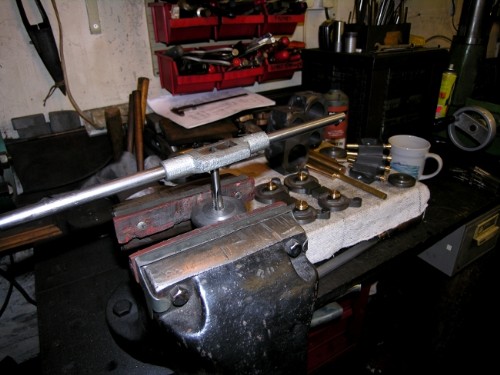
Soon had four holes threaded and then started making the bases for 4 simple lubricators with screw caps for the top lids.
Close of play. 4lubricator bodies started on. They're ready for finishing the top, boring out and threading for a 3/8" screwed cap with gasket. I promise I'll use the correct tapping drill this time!
Stanley Challenger Graham
Barlick View
stanley at barnoldswick.freeserve.co.uk  |
Stanley
Local Historian & Old Fart
36804 Posts
|
|
Posted - 25/09/2011 : 07:15
By the way. Daughter Susan visited and as she was leaving she saw the bits on the bench and said that they were lovely, looked like small sculpture or even jewellrey. Nice! They're beautiful to me of course but for different reasons. All part of the serenity of the shed, very satisfying to be actually making something! If there's one reason for these complicated posts it's to try to get others enthused about making stuff with your hand and eye. It doesn't matter what it is or at what level, it's good for you! Have a go!
Stanley Challenger Graham
Barlick View
stanley at barnoldswick.freeserve.co.uk |
Invernahaille
|
Posted - 25/09/2011 : 13:33
Stanley,
Neccessity is the mother of invention. I do like your set up in the shed. I could really have some fun in there. I would have thought the local textile museums would have kept you busy making spares for them.
I know that one of the ex managers from Wm Tathams in Rochdale, makes a healthy living dealing with textile spares. I think he is based in Bradford, somewhere.
Edited by - Invernahaille on 26/09/2011 12:41:10 AM
|
Stanley
Local Historian & Old Fart
36804 Posts
|
|
Posted - 26/09/2011 : 06:42
I used to be asked quite often but I think they perhaps think I'm dead now. See below for yesterday's activity. I reckoned up the number of operations for each sclinder lid luricator.... 18 and some setup changes. No wonder tiddly bits take time!
Stanley Challenger Graham
Barlick View
stanley at barnoldswick.freeserve.co.uk |
Stanley
Local Historian & Old Fart
36804 Posts
|
|
Posted - 26/09/2011 : 07:18
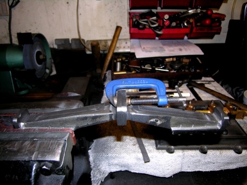
A trick I learned from Newton. Nobody can guarantee perfect alignment when freehand tapping in small sizes. Grab the tap in the tail stock chuck, have the taper just free but rubbing and follow the tap up as you go. Result, dead centre and correct allignment every time.
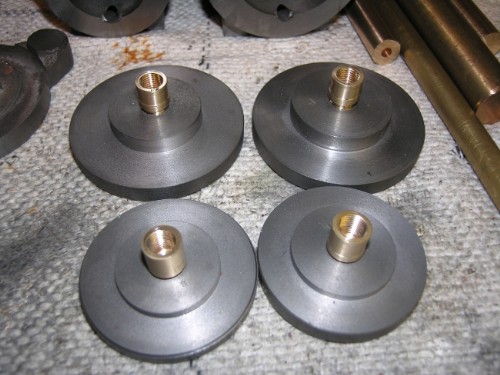
Four bodies ready for plugs.
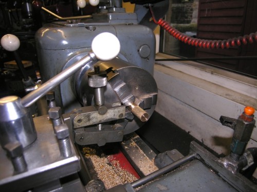
When you have a few hours to spare, make yourself a knurling tool. Single wheel knurls are a waste of time, they involve too much pressure on the workpiece. Find a design like this with opposing knurls and floating jaws which mean the tool self-centres. Set to the right diameter and run it in as hard as you like. As long as the chuck has a firm hold it'll work like magic and once it has started cutting is self adjusting. You can even force it to traverse. Result is nice knurled finish. Different knurl patterns give different finishes of course.
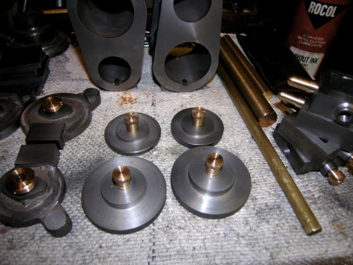
Close of play. Four plugs made and fitted with a tiddly neoprene ring at the base of the thread on each of them to ensure they are airtight. Minimum of 72 operations. Bugger the tiddly bits!
Question now is what to do next.... I hate studding and I know I've been shying away from it so I think I'd better bite the bullet, Daft as it sounds there are at least 250 studs in the cylinder blocks. Oh dear! All to be located, drilled, tapped and correct length studs fitted. I shall resist copping out and going onto valve-making!
Robert, I never thanked you for the compliment you paid the shed. You would love it, small, so everything is to hand and the funny thing is that when I first moved the machines in I was under pressure, in a hell of a rush and somehow managed to get everything in the right place! I think there must be some sort of instinct that guides us in things like this. I've often wondered how it could be improved but haven't found anything yet. Newton loved it and said it was the best shed he had ever seen, mind you he thought the carpets were cissy but agreed when I said it meant there was less chance of breaking something if you dropped it. What he particularly envied was the central heating and the fact it was in the house. Never any condensation or rust problems. He also laughed at the number of times I cleaned up and vacuumed the carpets! I used to tell him "Cleanliness is next to dirtiness!"
Stanley Challenger Graham
Barlick View
stanley at barnoldswick.freeserve.co.uk |
Stanley
Local Historian & Old Fart
36804 Posts
|
|
Posted - 27/09/2011 : 08:03
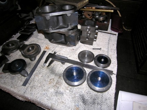
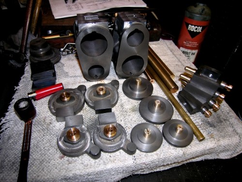
Close of play yesterday, four top lids marked for drilling.
I've started at the end today because I'm going into bleeding obvious mode for the benefit of those who may be learning. Four lids don't look like a heavy days work but a lot lies behind them. Bahrett's engine doesn't give a lot of help because he had some peculiar ideas. He had 9 holes in his HP lids, never seen an engine with an odd number. He also had 5/32" studs. I ditched that one straight away and mine will be 2BA, that's 3/16" clearance holes and obviously a slightly smaller tapping size, there is enough meat in the casting for this size. I also had a rethink and my reasoning based on Bancroft engine and the scale was wrong, 24 and 16 was too many, it would have looked fussy and got me into problems when studding near the steam passages. You have to bear this in mind, not a good plan to be drilling stud holes into voids! So, after a lot of thought and measuring up I settled on 12 in the LP and 10 in the HP. This gives a similar distance between stud holes and spans the inlet voids nicely.
A word here about stud positions. There is a convention in flange and lid alignment called 'template way'. It originated in erecting long runs of flanged piping and incidentally explains why even numbers of studs are almost always used. Imagine you're erecting horizontal flanged pipes and want to be sure your stud hole position matches perfectly from one legth to another. If you have a pair of holes at the top you can pop two bolts in, lay a spirit level across them and ensure a correct position of the first pipe. If the flanges match at each end you are sure you're going to get it right. On vertical pipe runs this convention is also used but not using the spirit level. Look at any horizontal engine and you'll see that the top two studs are template way, the same convention is used on vertiical cylinders with the two stud holes template way at the steam inlet. Mr Bahrett must not have thought this important.
Right! we have our stud sizes and numbers sorted, first thing we have to do is decide on the Pitch Circle Diameter. This has to be a balance between making sure the stud hole has enough meat round it in the casting and avoiding untidy set ups where the nuts overhang the edges of the lids. Once you have decided on this compromise, mark the PCD on the lids using a sharp pointed tool. That's one parameter clearly marked. The groove of the PCD marking is no problem as in full size practice matching faces like this are often grooved because it gives the sealing ring or compound a key into the face and makes a better seal.
Incidentally, Walt Fisher once told me that after failure of packings leading to severe scalding incidents on the footplates of locomotives, many railway companies stipulated ground faces and compound with no packings on footplate flamges. The idea was that if a packing blew it was such a small orifice that catastrophic scalding couldn't happen.
Now then, we get to the meat. There are lots of occasions in engineering where a circle has to be divided exactly into a specific number of segments, gear-cutting is the main one but of course equidistant stud holes are exacly the same thing. When I worked for Rochdale Welding I was often given the job of making one-off blanks for very large holes which had to be plugged for hydraulic testing and it was quicker and cheaper to make one rather than order a special. I can tell you that there is more to measuring and marking stud holes by hand than meets the eye! In the very early days this was how the first gears were marked out as well but the fitters soon found an easier way. The most simple way was to put a gear with the same number of detents as the stud holes you wanted on the tail of the lathe mandrel, rig up a detent and rotate the lid or flange held in the chuck past a fixed drill on the PCD and mark the workpiece for each position. Perfectly acceptable as long as the template gear was accurate and the first dividing was done this way. Still a good way out if you haven't any specialised gear. Johnny did a lot of gear cutting this way using loom gears which were easily available in every imagineable size. Another trick is to drill a dividing circle round the perphery of the back plate in the chuck. Newton treated one of the chucks in his Little John lathe like this to give him common divisions.
However, the old fitters soon realised that if they drilled the face of the largest gear in the headstock with concentric rings of different numbers of holes they could fit up a permanent detent mechanism and make the job easier. Different combinations of numbers were used for the rings, a favourite was 100, 96., 90, 68 and 12. If you think about it most common numbers are divisors of these numbers. Johnny used these on both his 1927 and his 1952 lathes. However, he soon went one better and we need to look at how I divided these PCDs on the lids.
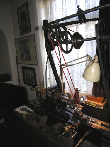
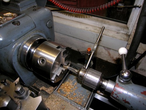
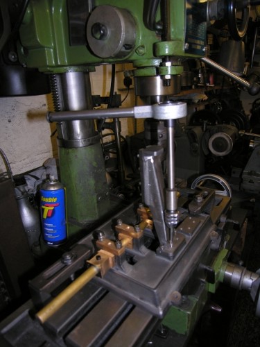
I could have done the lids on the big lathe but decided to use the 1927 lathe so I could show a different overhead gear. This the old fashioned way of getting a drive to a toolpost drilling or milling head. You disconnect the drive belt to the headstock and use a stepped pulley via a counterweighted tension pulley to drive the toolpost drilling spindle. Remember that there is no need for a drive to the headstock as it is stationary and held in plce by whatever dividibg gear you use. One thing I learned yesterday was that the red plastic driving rope I use doesn't like ultra violent light! The rope I had left wrapped round the spindle had perished and I had to make another one, lesson learned!
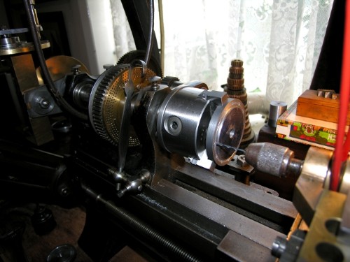
The LP lids were dead easy because I had a 12 hole register on the dividing plate fitted on the front of the largest pulley in the headstock. I think you can see the spring loaded detent arm fixed on the front of the bed. I could have done the HP lids, 10 stud holes, using the 100 hole register, just move ten holes at a time but for the purposes of demonstration used the tangential dividing gear to give you a look at how it works.
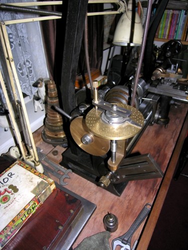
Here's the little beastie. In this pic the worm is not in gear with the large permanent 180 tooth worm gear on the tail of the mandrel, it's slid in and out on a guide which can be locked. The worm gears could be different sizes but Johnny favoured 180 teeth because each tooth is 2 degrees of rotation and it came in handy for scribing scales for his lathes, microscopes etc. Just for the moment, forget about the top dividing plate. If you think about it, 10 stud holes needs 18 complete turns on the handle controlling the worm. The top plate is locked and if you drop the detent into the same hole on the plate each time you have a perfect 10x register. Thats how I marked the 10 stud holes.
Now then, lets go a bit further (but not too far as it is a subject all on its own). The top plate under the worm handle is another dividing plate. It has concentric rings of 30, 28,27, 26, 12,and 11 holes. Think about the division you'd get if you advanced the worm handle 1 division of the 30 ring on the top plate you would have 5400 divisions. Different combinations of turns and holes give you different numbers and there is a further kick. If you use the spectacle plates on top of the division plate to advance the detent hole you are using by the same increment each time you open up a further range of combinations and resultant divisions. There is more, there is more that one dividing plate for the top register. Alright, it's mind boggling but the result is that using tangential dividing gear and the correct combinations of worm wheel, number of holes in the scale ring and a variable advance using the spectacleplets you can divide a circle into any number of holes, odd or even. Impressive or what?
Right, sorry about the length of that but knowledge has to be passed on! If you want more, there are books on dividing which will give you all the calculation methods and if it's any consolation, I used a similar tangential dividing gear on a special head I made for the VM to make all the replacement gears I needed for the 1927 lathe when I was refurbishing it. I had to get the book on dividing out and read it all up again to remind myself of how to use the gear. No shame in that!
Today I have to do some more thinking because the fact that the bottom lid incorprates the fixing points for the cylinder block to the standards and some of the studs are part of the fixing I have some thinking to do before I use the top lids as registers for marking the botton lids. It ain't easy!
Stanley Challenger Graham
Barlick View
stanley at barnoldswick.freeserve.co.uk |
Stanley
Local Historian & Old Fart
36804 Posts
|
|
Posted - 29/09/2011 : 10:26
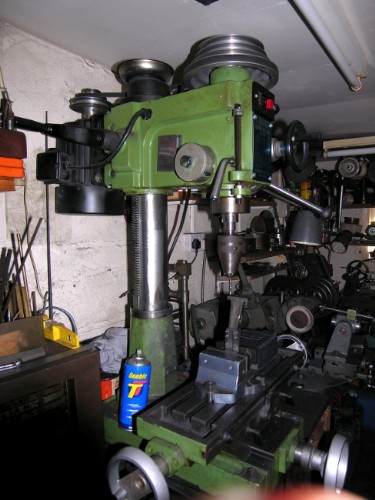
Catching up today. Tuesday started with putting johnny's Cardinal chuck on the VM. Not as easy as it looks, I had a hell of a job safely freeing the taper on the milling chuck, it was as fast as a thief!
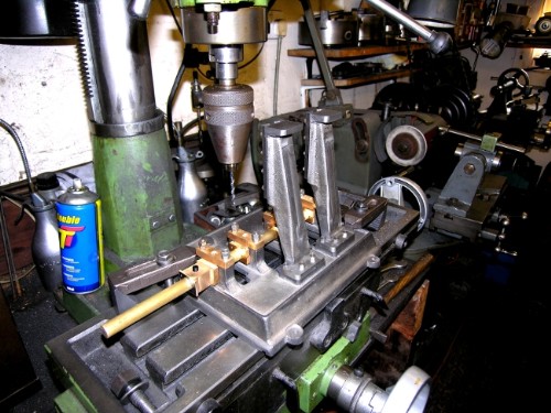
Today's job is fixing the standards onto the beds in the correct position so the first thing to do was to make sure I knew where the centre line was for each cylinder. So, a piece of half inch brass located in the bearings and popped at the right cylinder centres. This will do for both beds as they are identical.

First stage was to get one standard drilled in the correct position. Four 2BA set screws for each standard. I've fitted the VM up for drilling because it is more accurate than the pillar drill and there is a lot of drilling to do for stud holes and I want to be as accurate as possible.
Stanley Challenger Graham
Barlick View
stanley at barnoldswick.freeserve.co.uk |
Stanley
Local Historian & Old Fart
36804 Posts
|
|
Posted - 29/09/2011 : 10:53
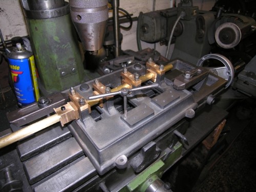
Once one standard was drilled in the correct places the same drillings were transferred to the next one by popping through the holes with an Eclipse automatic punch. Then more careful drilling.
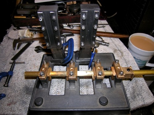
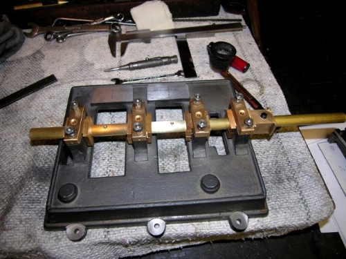
Clamps galore and some careful adjustments before marking one hole in each standard. Then drill and tap that hole, fix the standards using one set screw and mark the other holes after making sure that the standards are properly positioned.
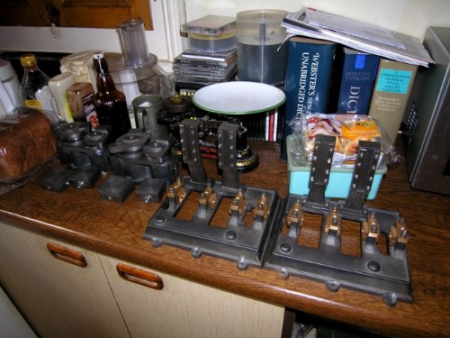
Close of play yesterday, two standards fixed and near enough in line. Lots of tiddly little adjustments like filing some off the base of one standard to get the slides absolutely vertical. I can cope with a slight discrepancy in the distance from the shaft centre when I make the cross heads but there is no way to compensate for slides that aren't vertical. It struck me while I was doing this that the old engine fitters would be laughing at me. They were doing this every day and would know all the tricks. I'm having to make it up as I go along. Still, that's part of the fascination.
Right, that's a morning in the shed blown away but we are up to date! Overtime this afternoon? (I know what Robert will say: "Work you bugger! This wouldn't have happened in my day!")
Stanley Challenger Graham
Barlick View
stanley at barnoldswick.freeserve.co.uk |
Invernahaille
|
Posted - 29/09/2011 : 18:07
Nice work Stanley,
You take a break.
|
Stanley
Local Historian & Old Fart
36804 Posts
|
|
Posted - 30/09/2011 : 05:11
The workforce refused afternoon duty and went to the pub Robert. I will whip them in for an hour or two this morning! Thanks for the comment..... Praise indeed.
Stanley Challenger Graham
Barlick View
stanley at barnoldswick.freeserve.co.uk |
Invernahaille
|
Posted - 30/09/2011 : 22:34
Truth is Stanley, I have not been hands on for years now. I think I am as rusty as hell. You know the old expression use it or lose it.
Its just good to see someone using these skills.
Thats what happens when you rise up the ranks. Learn leadership skills. I know what I want you make syndrome. I have never asked anyone to do something I couldnt do myself. The only difference now is that it would take me many times longer.
|
Stanley
Local Historian & Old Fart
36804 Posts
|
|
Posted - 01/10/2011 : 07:46
Robert, I don't think you lose the skills, they are dtill there and only need wakening up. I have to keep looking at thread and conversion tables to remind myself of sizes, it used to be automatic.
Stanley Challenger Graham
Barlick View
stanley at barnoldswick.freeserve.co.uk |
Stanley
Local Historian & Old Fart
36804 Posts
|
|
Posted - 01/10/2011 : 07:53
Despite the stress of having to scrub up and get ready for a night out in Bradford the staff put in a full morning on the standards for the second bed. All standards drille for clearance, tapping holes marked and drilled and tapping started. One thing Newton taught me, the smaller the tap the smaller the tap wrench, you break less taps that way! Onwards and upwards. It's slow but we are making progress!
Stanley Challenger Graham
Barlick View
stanley at barnoldswick.freeserve.co.uk |
Stanley
Local Historian & Old Fart
36804 Posts
|
|
Posted - 01/10/2011 : 10:52
I didn't get a lot of sleep last night so no heroics today, I know my limitations!
First job was to finish tapping the holes for the standards in the be4d and then fit them. Just one hole slightly out, don't start filing clearance holes out, jusyt pop the tap in and clean the thread up. Of course the standards were in the way so another little toy comes out.
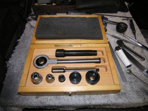
One of the advantages of going into engineer's stores regularly is that every now and then there will be something on offer. This set of Draper tap holders was £4 I think and whist not in use often, when you need it a lot of time can be saved. Same applies to the .009" shim I needed for one of the standards to get it dead level. I have a box full of shim steel, all bought cheap in clearance sales. One of the advantages of the decline of general engineering is that stuff like this can be dirt cheap.
Close of play. Both beds have the standards fitted, all vertical and lined up with each other. So a bit of a think now... I think that we have to start studding on the cylinder block because it isn't until I have got that done that I'll know how to treat the tricky junction between the studding of the bottom lids and the top face of the standards because they interfere with each other. I'll stud the top lids and the steam chests while I think about that one. A quick clean up in the shed, a straight edge for tomorrow. Now for a walk and lunch. Not a bad morning's work! (Smug bastard!)
Stanley Challenger Graham
Barlick View
stanley at barnoldswick.freeserve.co.uk |
Invernahaille
|
Posted - 01/10/2011 : 12:10
Stanley,
The draughtsman and drawing board are long since gone. These days its cad/cam and 3D Solidworks etc. Engineers produce drawings that have DX files, The dx file is a programme that CNC machines use. The skill now is being able to read programming languages, and the ability to input data to the machine tools computer.
The real engineering is in the computer drg programme.
You seem to have worked without drawings, using only, the idea in your head to interpret what you required.
That is engineering.
|